---
url: >-
/statelake/tutorials/tutorial-exercises/tutorial-3-import-xml-purchase-orders-into-a-database.md
---
# Tutorial 3: Import XML Purchase Orders Into A Database
This document illustrates mapping into related database tables. The source data will be an XML file, and the destination database will be the same Exo database that we have already worked with, **MYOB Exo**.
This tutorial represents a case of a supplier receiving electronic purchase orders and automatically processing them into Exo, along with some order validation.
Each step should be fully completed before processing to the next. The topics covered are:
* Configuring XML **File Definitions** to enable the reading of XML files
* Configuring the database **DB Definitions** for writing into related database tables
* Using variables in the **Statelake Map**
* Using various events in the **Statelake Map**
* Querying databases from the **Map** during processing
* Control of the execution of the **Map**, and halting the processing
It is most important before you proceed, to check and ensure that all of the training files have been copied as instructed. These files are an essential part of this tutorial.
## XML Files
XML files differ from flat data files because they contain information scattered within the file that relates to the file structure, interspersed with the actual data values. This format tends to make XML files larger in size, but can also make them easier to read.
For example, an order number in an XML file might appear as:
```xml
12345
```
XML also has the advantage of using schema files. These are separate from the data files, and describe the structure of the incoming XML data file, along with any validation rules that each data file must comply with.
The format of these schema files determine how the incoming data is translated and typically have a file name ending with .xsd, whereas XML data files have an .xml file extension.
The following examples show a simple XSD schema file, and the corresponding XML data file.
### Simple XML Schema Definition (.XSD) For An Order
```xml
```
### Simple XML Data File (.XML) For The Same Order
```xml
12345
26-10-2011
1
ABC
10
2
XYZ
3
```
## Where The Data Is - Database Connections
In this tutorial, an Exo database will be used as the destination, so the **DB Connection** to the Exo database **MYOB Exo** that has already been established in earlier tutorials can be used, as the information is the same. We do not need to re-create or duplicate it.
The first step is to make sure that **Statelake** module **Designer** for your selected configuration **Statelake_Training** is open. An expanded structure tree will be displayed on the left side of the screen.
1. Follow the path **Configuration > Components > Data Connections > DB Connections**. Click on **DB Connections** and **MYOB Exo** should be displayed.
## Where The Data Is - File Connections
As we know, the **File Connections** module also sits under the **Data Connections** umbrella, and is the configuration module that points to a specified file directory that can hold either or both the source file or destination file. In this tutorial, the output file will be an Exo database, and the source will be a file. So a new file connection for the input/source file needs to be created.
**Designer** will already be open. If not, open the **Statelake** module **Designer** for your selected configuration. An expanded structure tree is displayed on the left side of the screen.
### Create File Connection
1. Follow the path **Configuration > Components > Data Connections > File Connections**. Right‑click on **File Connections** and choose **New** from the drop-down list.
2. A new item called **New File Connection** will appear in the structure tree. In the **New File Connection** window the following information is to be entered.
1. **File Description** – the name that is meaningful and best describes the file. In this tutorial the description given this connection will be **Mitre10: Purchase Order**.
2. **File Directory** – the directory location of the file. Enter \\Mitre10 Orders. Use tab to exit the field and move on.
::: info
The \ tag refers to the default file path already set-up within **Statelake General Setup**, under **Global Setup**. By default, **C:\ProgramData\FlowSoftware\Statelake\Files** will be the file directory referenced by this tag, and selected.
:::
c. **Audit Directory** – will be automatically populated when you tab out of **File Directory**.
d. **Error Directory** – will be automatically populated when you tab out of **File Directory**.
::: info
**Statelake** uses two sub-directories to manage files - AUDIT and ERROR. When a file is successfully processed in, or successfully sent after bring written out, it is moved into the AUDIT directory. If an error occurs during file processing, the file is moved into the ERROR directory.
:::
e. **File Name** – the actual name of the file. In this tutorial, leave this field blank as this connection will not be used to produce any new files – we just want to read from the file.
f. **File Search Pattern** - used by **Statelake** when files are being read. Enter **M10\*.xml** to locate all files that match this search criteria. This should locate the three XML files called **M10 Order.xml**, **M10_41919.xml**, and **M10_41920.xml** that are to be used for the source. The asterisk \* is a wildcard and replaces any letter in the search. Each of these XML files contain data pertinent to orders.
g. **Ensure Unique File Name** – tick this box to add a number to the file name to ensure that the file name will be unique and will not overwrite a file already in the output folder.
h. **Allow This File To Be Accessed** – for this tutorial leave unticked.
3. If the sub-directories you have specified do not yet exist or you are not sure whether they exist, you will need to check by clicking on the button **Create Dirs** which is located on the top left of the window.
4. If they do not exist, they will be created, else they will be confirmed as current and available by display of the pop-up message “**File connection directories checked/created successfully**”. Click **OK** in response to the successful creation message.
5. Click **Save** when all details are entered to save and close the module.
The File Connection named **Mitre10: Purchase Order** will now appear in the structure tree under **Configuration > Components > Data Connections > File Connections**.
## What The Data Is - Creating File Definitions
The **File Definitions** module is used to design the structure of the files that are either read from, or written to the **Statelake** configuration. There are four types of files that can be specified in this module - “flat” text files, XML files, Excel (binary), and EDI (EDIFACT) type files. Unlike the flat file that was created in tutorial one, this tutorial uses an XML file as the source. The file is a purchase order file in XML format, and as such the definitions are entered in a different sequence to tutorial one.
::: info
**EDIFACT** is an acronym that stands for Electronic Data Interchange For Administration, Commerce and Transport. It is a more specialised file type that is used in global data transfer, with rules ratified by the U.N.
:::
In this tutorial, a multi-tier XML definition for the input or source purchase orders schema .XSD file and data .XML files will be created.
**Designer** will already be open. If not, open the **Statelake** module **Designer** for the selected configuration. An expanded structure tree is displayed on the left side of the screen.
### Create File Definition
1. Follow the path **Configuration > Components > Data Definitions > FIle Definitions**. Right‑click on **File Definitions** and choose **New** from the drop-down list.
2. **New File Definition** will appear as an item in the structure tree. In the **New File Definition** window the following information is to be entered under the **General** tab. We will not be accessing the **Partner Identification** tab during this tutorial.
1. **File Type** – select **XML File**.
2. **File Definition Name** – the default is **New File Definition**. Enter the definition name of the source file, as specified during the creation of the **File Connection**. In this tutorial it is **Mitre10: Purchase Order**. Make sure that it is typed precisely.
3. **DB Connection** – right-click anywhere in the blank **DB Connection** box to see the **Add** pop-up, and a list of all the found connections will be displayed by following the arrow. Select the one you want from the list – in this tutorial, it will be **MYOB Exo**. A source database is required to be selected for all definitions.
::: info
If you select the wrong **DB Connection**, simply double-click on the name within the box to de-select it, and start again.
:::
d. **File Connection** - select **Mitre10: Purchase Order** from the pull-down list.
e. **Disable Automatic String trim** – leave with the default tick as set.
f. **XSD Schema** – either click the **3-dot ellipse** to navigate to the directory where the schema files were copied and select **PurchaseOrderFull.xsd** by clicking on **Open** or enter the path name as <**DefaultDir>\Mitre10\PurchaseOrderFull.xsd**.
::: info
When working with XML files, **Statelake** will always require schema files (XSD), not only to define the structure of the file, but also for validation purposes when reading from, or writing to, an XML file.
:::
g. Resolve Imported/included schemas (recommended) – leave as ticked.
h. All other fields and tick boxes are to be left as defaulted.
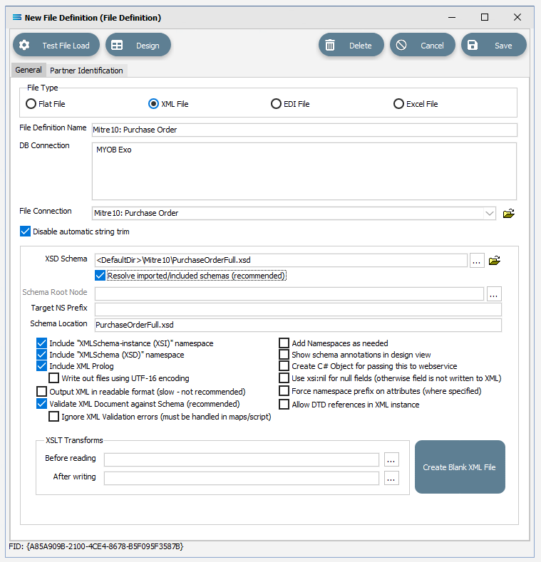
3. Click **Design** in the top left of the window.
### Create File Dataview Query
1. A blank definition designer canvas will display. To start creating the contents of the file definition, click on the **File** menu in the top left corner, and choose **New** (or use the Ctrl+N).
2. The **New Items** window will open and only two items called **XML Dataview** and **DB Dataview** will be displayed.
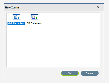
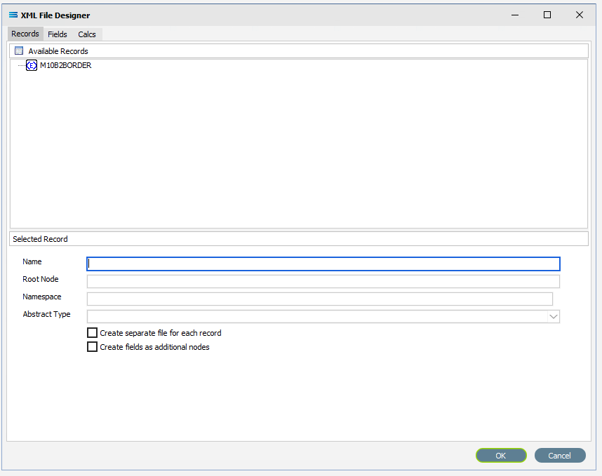
By default, **XML Dataview** should be highlighted. If not, select **XML Dataview** and click **OK** to add a new **XML Dataview**. The **XML File Designer** window will open. Expand this window if required, to ensure that the **Available Records** and **Selected Record** panes are both displayed fully.
::: info
The **Records** tab will automatically populate some records or elements. There are read from the schema file that you identified on the initial window.
:::
### Create M10B2BORDER Root Node
In a tree structure, the **Root** node is either the topmost or the very bottom branch, depending on how the tree is represented visually. It is the master or starting point – the point from which everything else stems and represents the ultimate objective or main choice. Then there are the **Branches**, which stem from the root and represent different options, and the **Leaf** node, which are the last options attached at the end of the **Branches**.
In the **XML File Designer** window there are three tabs – **Records**, **Fields** and **Calcs**. In this tutorial, the **Records** tab will display **M10B2BORDER** in the **Available Records** pane. If there are multiple entries, scroll down until **M10B2BORDER** is highlighted and double-click on it to select. **M10B2BORDER** is the **Root Node**.
1. The **Name** and **Root Node** fields in the lower **Selected Record** pane will be automatically populated. **M10B2BORDER** will appear in the **Name** field, and \M10B2BORDER will populate the **Root Node** field.
::: info
**Root Node** in this context is the parent element or file identifier for the group of fields and records that you are adding to this dataview. You will see that the path to the fields will be constructed based on the **Root Node** you specified.
:::
2. All other fields and tick boxes are to be left as the set default.
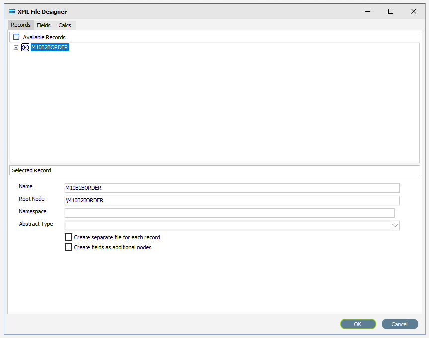
3. If it has not already been expanded, then click on the plus to expand **M10B2BORDER** in the **Available Records** pane.
::: info
The structure in the schema file **PurchaseOrderFull.xsd** determines how these field relationships are handled within this XML **File Definition**. The top level in the file structure tree is referred to as the **Root Node** - the name given to the envelope that holds the group of source records. It is the start of the structure tree. In this tutorial, **M10B2BORDER** is the name given to this group of purchase orders.
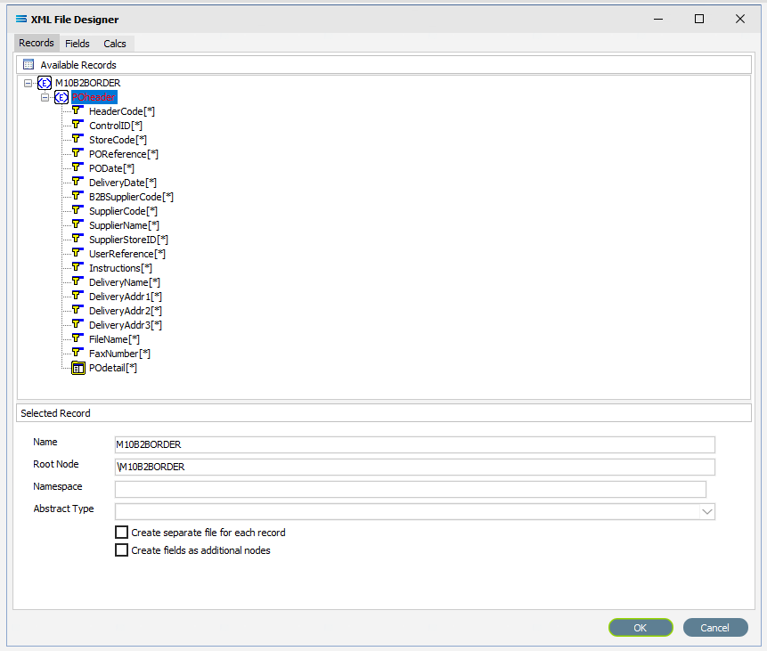
The **POheader** is a node that branches off the **Root Node**. It is the parent for each XML record and in this tutorial, identifies the fields within each purchase order header. This is a “fat” Branch.
One of the field items in **POheader** is called **POdetail**, which is a dataset or group of records in its own right, with its own set of fields, and this is also a Branch - albeit a “twig” off the “fat” Branch. If you wish, you can think of it in this instance, as a **Leaf Node**. In this tutorial each **POheader** record can contain multiple **POdetail** records.
The asterisk (\*) at the end of the field name means that you can have more than one of these fields in a single record. There is no limit.
A **RED A** at the end of the field name identifies the field as an attribute.
:::
There are currently no fields available in the **M10B2BORDER** root node, but there is a **POheader** which is displaying in **RED** because this is a compulsory record.
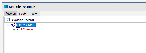
On the occasion that there are fields under the **Root Node** itself, they could record information such as who sent the file, when it was sent, and the receiver identity – information that only refers to the file as a whole and is not required more than once. Such fields would be ignored.
::: info
There is a symbol to the immediate left of the field name. A BLUE \ signifies that the item is a non-repeating complex element (a record). A folder icon identifies a repeating complex element (record). A **YELLOW T** indicates a simple element (a field),
:::
4. Under **Available Records**, click on **POheader** or click the symbol beside it to expand this group (the “fat” Branch), to show the fields within this record grouping. It shows that the header for each record can have multiple fields such as **StoreCode** and **SupplierCode**. Expand the window or drag the separator bar between the panes down if required to enlarge the **Available Records** pane.
5. The last field in **POheader** is **POdetail** which has a series of fields in its’ own right – it is a “twig” or **Leaf Node**.
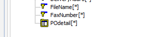
Click on **POdetail** or click on the symbol beside it to expand it and view the fields under this record grouping. It shows that for each detail field, there can be one or more detail lines that has its own series of fields. Scroll up and down to see them all if required.
6. Move to the **Fields** tab in the **Available Fields** pane and all the fields grouped under **POheader** and **POdetail** will be displayed in the upper **Available Fields** pane.
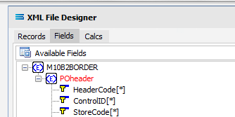
7. While **POheader** and **POdetail** appear in the **Available Fields** list, they are simply the name or identifying label for the group of fields within them, and are to be treated as such and are to be ignored for selection. With the exception of the group label **POheader** and **POdetail**, add all of the fields from the **POheader** element only by double‑clicking on each field in turn. Once selected they will appear in the **Selected Fields** pane, showing the data type, length, and XPath of each selected field. As you select the fields, they do not disappear from the **Available Fields** list.
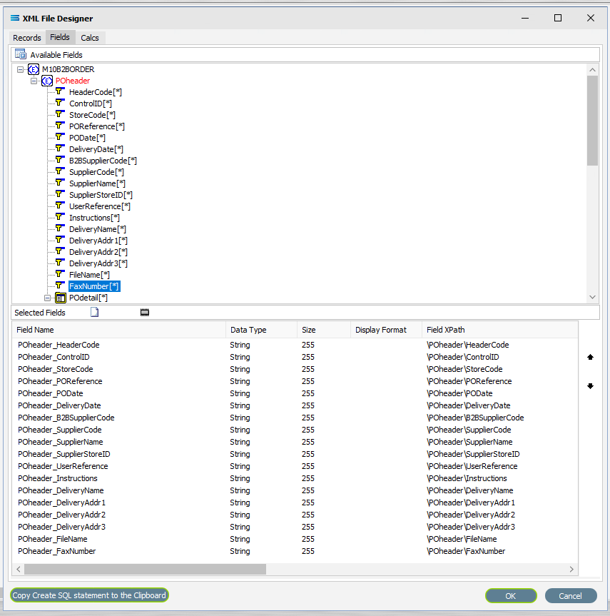
8. The first field should be **POheader_HeaderCode**, and the final field to be selected should be **POheader_FaxNumber**. Expanding the window will only expand the **Available Fields** pane. In the **Selected Fields** pane, all fields will be prefixed with POheader\_ (the word POheader and an underscore) to identify the original record.
::: info
If you want to select two instances of the same field, click on the field name in the **Available Fields** pane for each instance. The second and subsequent selections will appear in the **Selected Fields** pane with a sequential number appended to the end of the field name.
:::
::: info
If you make a mistake and click on one of the fields in the **Available Fields** pane that you do not actually require, or click on a field more than once in error, to de-select it, simply double-click on the field name in the **Selected Fields** pane that you do not want.
:::
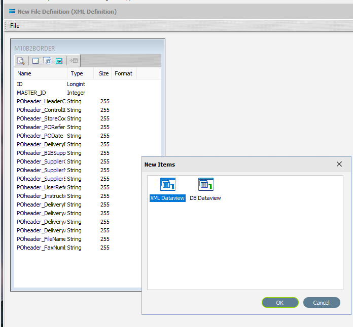
9. Click the **OK** button to save and close the window. You will return to the Mitre10: Purchase Order (XML Definition) canvas and a definition window named **M10B2BORDER** will be visible identifying those fields only contained within **POheader**. Expand the window as required.
10) The folder icon that was visible beside **POdetail** on the previous screen showed that this item was repeating within the header record – meaning that there were multiple detail records for each header record. Therefore, it is treated as a node in its own right and in **Statelake**, will be shown as an “**expanded**” **Root Node**. Create another **XML Dataview** for this node **POdetail** by clicking on the **File** menu in the top left corner, and choose **New** (or use the Ctrl+N).
11) The **New Items** window will open and again, only two items called **XML Dataview** and **DB Dataview** will be displayed. Select **XML Dataview** and click **OK** to add a new **XML Dataview**.
### Create PODETAIL Root Node
1. The **XML File Designer** window will open the Records tab and display **M10B2BORDER** with the expanded **POheader** and **POdetail** fields in the **Available Records** pane. **POheader** will appear in **RED**.
2. If the fields are not expanded, then double-click on **M10B2BORDER** to select and expand the records list. Scroll down to **POdetail** then double-click on it to select it, and populate the **Selected Record** pane.
1. The **Name** and **Root Node** fields in the lower **Selected Record** pane will be automatically populated. The **Name** will now say **PODETAIL**. The **Root Node** will now say \M10B2BORDER\POheader\POdetail. This signifies that the **Root Node** called **POdetail** is off **POheader** and within the **M10B2BORDER** envelope.
2. All other fields and tick boxes are to be left as the set default.
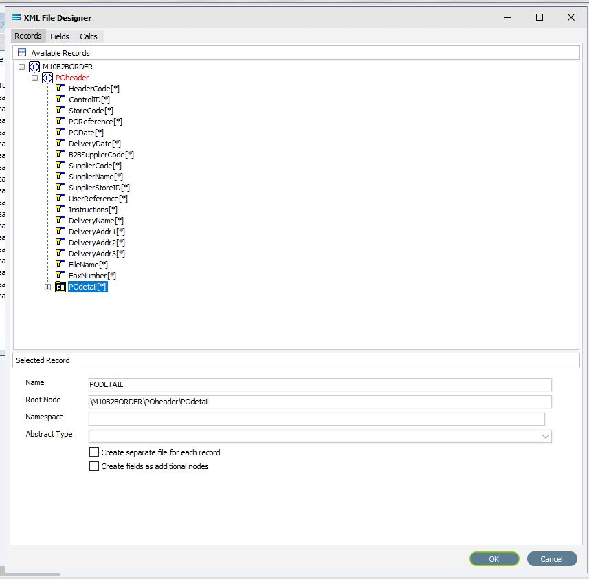
3. If it is not already expanded, either click on the **plus** or double-click on **POdetail** to expand this group and show the fields within this record grouping. Make sure the **Name** and **Root Node** do not change.
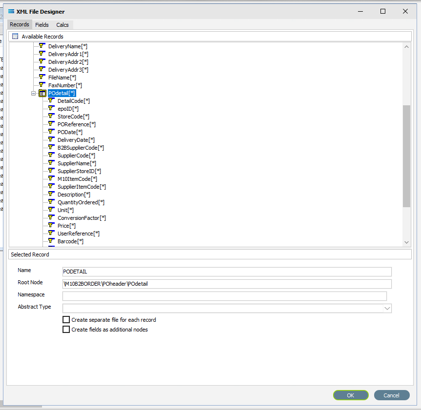
4. Move to the **Fields** tab, and all the fields grouped under **POdetail** will be displayed in the upper **Available Fields** pane.
5. For this tutorial, not all detail fields are required to be selected. Add the following fields to the **Selected Fields** pane only by double‑clicking on them in the **Available Fields** pane:
1. **DetailCode**
2. **M10ItemCode**
3. **SupplierItemCode**
4. **Description**
5. **QuantityOrdered**
6. **Unit**
7. **ConversionFactor**
8. **Price**
9. **UserReference**
10. **Barcode**
11. **Instructions**
6. In the **Selected Fields** pane, all fields will be prefixed with POdetail\_ (the word POdetail and an underscore) to identify the original record.
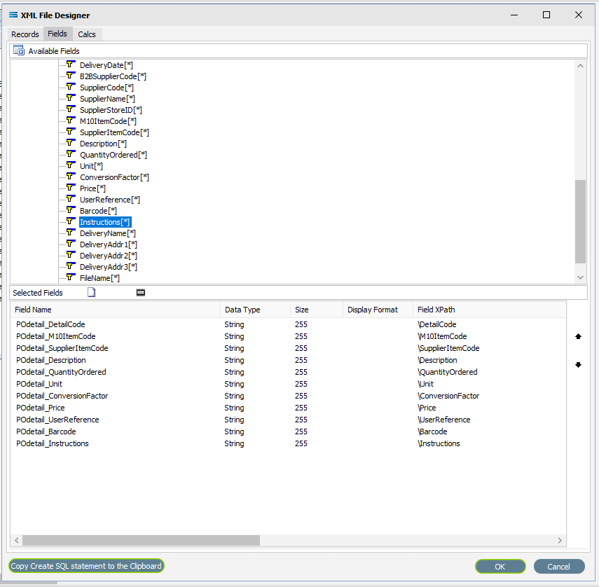
7. Click on **OK** to save and close the window. You will return to the Mitre10: Purchase Order (XML Definition) canvas and now there will be two definitions – one named **M10B2BORDER** showing the fields from **POheader**, and one named **PODETAIL** showing the selected fields from **POdetail**. Expand these windows as required.
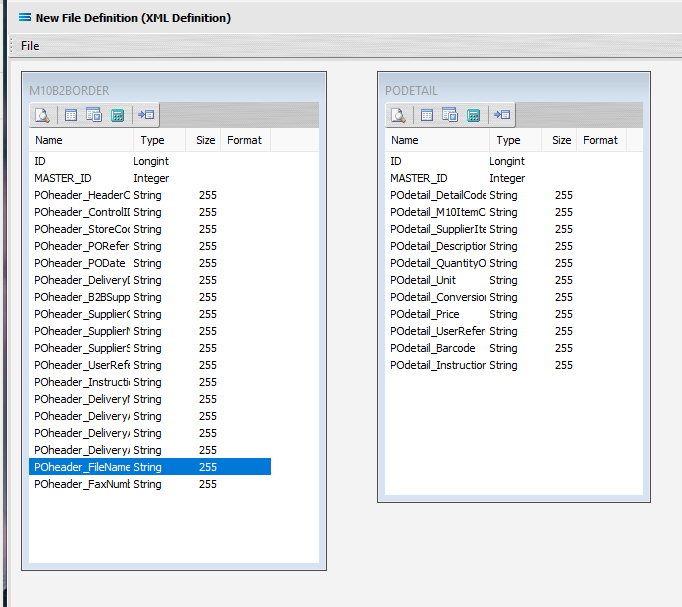
::: info
The extra fields **ID** and **MASTER_ID** in the dataview are automatically generated by **Statelake** to enhance the building of the file relationships, and are not included in the mapping process.
:::
### Link The Datasets
1. To link the two together (**M10B2BORDER** and **PODETAIL**), we add a relationship between the two datasets by dragging the **MASTER_ID** field from the **PODETAIL** dataview containing the fields from **POdetail**, and dropping it onto the **ID** field of the dataview **M10B2BORDER** containing the fields from **POheader**. Click on **PODETAIL_MASTER_ID**, drag it so that the label shows as per the example, then unclick to drop it.
2. Three things will happen. **PODETAIL** will be renamed to **PODETAIL linked to M10B2BORDER**. A one‑to‑many relationship link symbol will appear between the two dataviews - the one “single” link pointing at **ID** in **M10B2BORDER**, and the many pointing at **MASTER_ID** in the renamed dataview **PODETAIL linked to M10B2BORDER**. And **ID** in **M10B2BORDER** will be bolded, as will **MASTER_ID** in **PODETAIL**. The line of the link indicator will appear at the top of the item it is linked it.
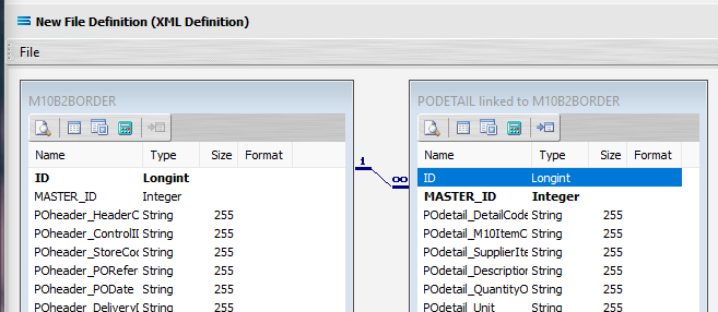
3. The links between the two datasets have now been successfully completed. Columns and window borders can be resized as required by dragging them with the mouse. Close the definition canvas by selecting **Close** from the **File** menu. You will return to the **File Definition** window. Click **Save** to save and close the **New File Definition** module. Always remember to select Save here – else all of your hard work linking these datasets will not be saved.
::: info
To ensure that the mapping will work as it should it is important to do a double check to make sure that your **File Definitions** are correct, and the parent/child relationship is described as it needs to be.
You can re-open the **File Definition** called **Mitre10:Purchase Order**, and click **Design** on the opening window. This takes you to the canvas where **M10B2BORDER** and **PODETAIL linked to M10B2BORDER** are displayed, along with their field link. Click on the **Records** tab on each dataset in turn to bring up the XML **File Designer** window for the respective dataset.
For **M10B2BORDER** - ensure that the **Name** is **M10B2BORDER** and the **Root Node** is \M10B2BORDER. Cancel to exit the window.
For **PODETAIL** - ensure that the **Name** is **PODETAIL** and the **Root Node** is \M10B2BORDER\POheader\POdetail. Cancel to exit the window.
If this is not correct, you will need to return to the previous three sections **Create M10B2BORDER Root Node, Create PODETAIL Root Node**, and **Link The Datasets** and do them again.
Then select **File** followed by **Close** to exit the canvas, then **Cancel** to exit the **File Definition** window.
:::
The **File Definition** named **Mitre10: Purchase Order** will now appear in the structure tree under **Configuration > Components > Data Definitions > File Definitions**.
You have now successfully created a file definition for an XML file type with a multi‑tier dataset.
## What The Data Is - Creating DB Definitions
The **DB Definition** tells **Statelake** what the data is, so that the proper fields can be accessed and the data extracted correctly, which means defining the exact information to be extracted. The **DB Definition** also identifies how the output file is to be constructed.
Sitting under the **Data Definitions** umbrella, **Statelake** uses the **DB Definitions** module to define these data structure components, and to design the database queries for both reading the data out of, and writing in to, the databases. Illustrating the subtle but important differences with this type of destination definition, this tutorial uses two related tables for the output, or destination.
**Designer** will already be open. If not, open the **Statelake** module **Designer** for the selected configuration. An expanded structure tree is displayed on the left side of the screen.
### Create DB Definition
1. Follow the path **Configuration > Components > Data Definitions > DB Definitions**. Right‑click on **DB Definitions** and choose **New** from the drop-down list.
2. The item **New DB Definition** will appear in the tree. In the **New DB Definition** window the following information is to be entered.
1. **DB. . Definition Name** – the name that is meaningful and best describes the query/extraction. We will use **Exo: Sales Orders In**.
2. **DB Connections** – this is the name of the source database, identified by the meaningful name that was given in the **DB Connections** module. Right-click anywhere in the box to see the **Add** pop-up, and a list of all the found connections will be displayed. Follow the arrow and select the one you want from the list – in this tutorial, it will be **MYOB Exo**.
::: info
Remember, that if you select the incorrect **DB Connection**, simply double-click on the **DB Connection** name within the box to de-select it and start again. It is very easy to correct.
:::
c. **Transaction Identification** – leave with the defaults as set.
d. **Duplicate Record Handling** – leave with the defaults as set.
e. **Disable Automatic String Trim** – leave with the default as set. This box is ticked.
f. **Save Null Fields as Blank Strings** – leave with the default as set.
g. **Disable SQL Transactions** – leave with the default as set.
h. **Save Blank String Fields as Nulls** – leave with the default as set.
i. **Include Null Values in SQL statement** – leave with the default as set.
3. Click **Design** in the top left of the window.
### Create 1st DB Dataview Query
1. A blank definition designer canvas will display. To start creating your query, click on the **File** menu in the top left corner, and choose **New** (or use the Ctrl+N).
2. The **New Items** window will open and only one item called **DB Dataview** will be displayed. Click **OK** to add **DB Dataview**.
3. The **Query Designer** window will open.
4. The first tab in the **Query Designer** is **Tables**. The upper pane contains a list of available tables in alphabetic order, and the lower pane will display the tables that you have selected during this process. Scroll down the available tables to **SALESORD_HDR** (Sales Order Header) and double-click to select it. It will appear in the lower pane as a selected table, while still remaining visible in the upper pane.
::: info
You may have to expand the window height to see a greater number of entries.
:::
5. Move to the **Fields** tab, and add the following fields to query by double-clicking on them. As each one is selected, it will disappear from the upper pane and appear in the lower pane. **SEQNO** will be displayed in **RED**.
6. If you make a mistake and select the wrong field, then simply double-click on it in the lower pane and it will de-select and reappear in the upper pane.
1. **SEQNO** (sequence number)
2. **ACCNO**
3. **ORDERDATE**
4. **DUEDATE**
5. **CUSTORDERNO**
6. **ADDRESS1**
7. **ADDRESS2**
8. **ADDRESS3**
9. **ADDRESS4**
10. **INSTRUCTIONS**
11. **SUBTOTAL**
12. **TAXTOTAL**
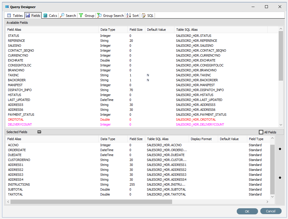
::: info
The fields are colour coded in the **Query Designer**. **RED** indicates that the field is either calculated or it is an automatically generated **IDENTITY** type, such as **SEQNO**. **PINK** indicates that the field does not allow null values.
:::
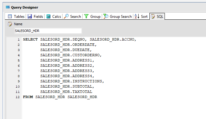
7. Click on the **SQL** tab to see the SQL query that has been generated. It lists the fields you selected and the table they are to be retrieved from. You will see that each field is prefixed with the table name with a full-stop as a separator.
8. Click **OK** at the bottom-right of the **Query Designer** to save the dataview and return to the definition canvas. The configured dataview will display, listing all of the selected fields. Expand this window as required.
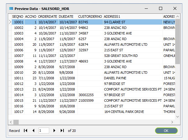
9) Click on the **Preview** button to run the query and see the results which will open in a specific window called **Preview Data – SALESORD_HDR**.
10. Click **OK** at the bottom of the preview window to return to the definition canvas and the open dataview.
### Create 2nd DB Dataview Query
1. Create another **DB Dataview** by clicking on the **File** menu in the top left corner, and choose **New** (or use the Ctrl+N).
2. The **New Items** window will open and only one item called **DB Dataview** will be displayed. Click **OK** to add **DB Dataview**.
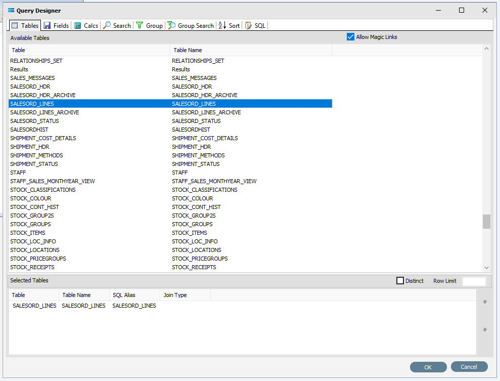
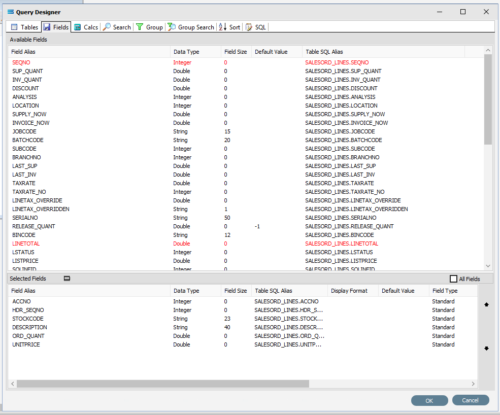
3. \13. The **Query Designer** window will open on the **Tables** tab. The upper pane contains a list of available tables in alphabetic order, and the lower pane will display selected tables. Scroll down the available tables to **SALESORD_LINES** (Sales Order Lines) and just as we did for the **SALESORD_HDR** table, double-click on the **SALESORD_LINES** table to select it, and it will appear in the lower pane as a selected table.
4. Move to the **Fields** tab, and add the following fields to query by double-clicking on them:
1. **ACCNO**
2. **HDR_SEQNO** (order header sequence number)
3. **STOCKCODE**
4. **DESCRIPTION**
5. **ORD_QUANT**
6. **UNITPRICE**
5. As you select fields from the **Available Fields** pane, they will appear in the **Selected Fields** pane, and disappear from the **Available Fields** pane.
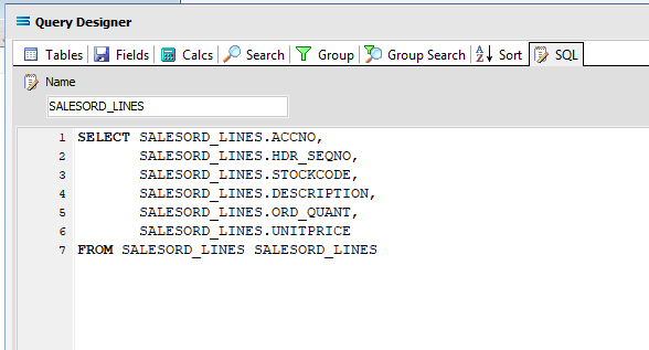
6. You can click on the **SQL** tab to see the SQL query that has been generated. It lists all of the fields you selected and the table they are to be retrieved from.
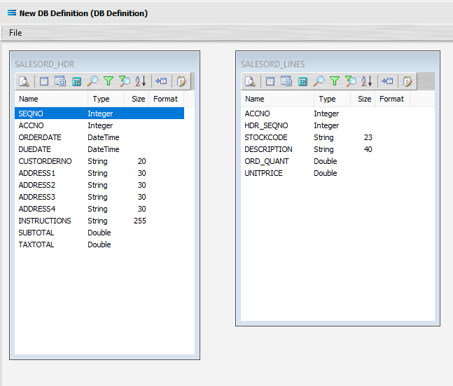
7. Click **OK** at the bottom-right of the **Query Designer** to save the dataview and return to the definition canvas. The configured dataview will display, listing all of the selected fields, so now there will be two definitions visible on the canvas - one named **SALESORD_HDR** and one named **SALESORD_LINES**. Expand the windows as required.
### Link The Datasets
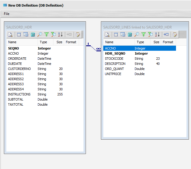
1. We want to link these together, so add a relationship between the two datasets by dragging the **HDR_SEQNO** field from the **SALESORD_LINES** dataview and dropping it onto the **SEQNO** field of the dataview **SALESORD_HDR**. Click on **SALESORD_LINES.HDR_SEQNO** and drag it over to **SALESORD_HDR.SEQNO** - once you see the drag label as below, then unclick to drop it.
2. Three things will happen. **SALESORD_HDR** will be renamed to **SALESORD_LINES linked to SALESORD_HDR**. A one-to-many relationship link will appear between the two dataviews - the “single” link pointing at **SEQNO** in **SALESORD_HDR**, and the many pointing at **HDR_SEQNO** in the renamed dataview **SALESORD_LINES linked to SALESORD_HDR**. These two linked fields will also be bolded.
3. Now we want to add some criteria. Either, click the **Search** tab on the **SALESORD_HDR** dataview to open the **Query Designer** window on the **Search** tab, or get to the same place by simply clicking on the **Tables** tab for the dataview, and when the **Query Designer** window opens, move to the **Search** tab. Expand the window as required.
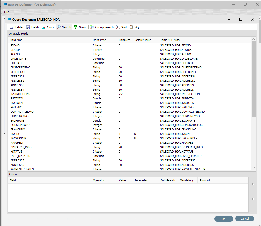
4. The upper pane shows the **Available Fields**, under the heading of **Field Alias**. Double-click on **SEQNO** in this list (SALESORD_HDR), and the field name will appear in **Criteria** pane. The field name will not disappear from the top pane once selected. To remove a field selected in error, simply double‑click on it in the **Criteria** pane to de-select.
::: info
To change the sort sequence of the field name list, click on the **Field Alias** column name to toggle the sequence. Click once to sort alphabetically from in descending order from A - Z; click again to toggle to ascending order from Z - A; click again to return to the default sequence (as per the table design).
:::
5. To the right of the field name in the **Criteria** pane, several extra fields will appear, including **Operator** and **Value**. Leave the **Operator** as defaulted as an equal sign (=), and enter -1 as the **Value**, to ensure that the **DB Definition** is empty when it is loaded into the map. If this dataset holds any data, then **Statelake** will produce an error, so to successfully insert or update data into a populated table, the search criteria is set to a value that will not exist in the table (such as -1), Tab out of the **Value** field.

::: info
**Statelake** will generate an error during the start of mapping if the destination dataset contains any data prior to the operation. So entering a value if minus 1 (-1) into the value field forces the destination dataset to be completely empty of any residual data.
:::
6. Now leave the **Search** tab and move left into the **Fields** tab. Under **Selected Fields**, under the **Field Type** column, all the fields that you selected earlier will be displayed and all will have a **Field Type** of **Standard**. **SEQNO** will be displayed in **RED**.
7. Change the **Field Type** on **SEQNO** to **Primary Key – Auto**, by clicking on the **Field Type** for the line and selecting this option from the pull-down list. If **Primary Key – Auto** does not display properly, then expand the width of the column. **Primary Key - Auto** should be first at the top of the list.
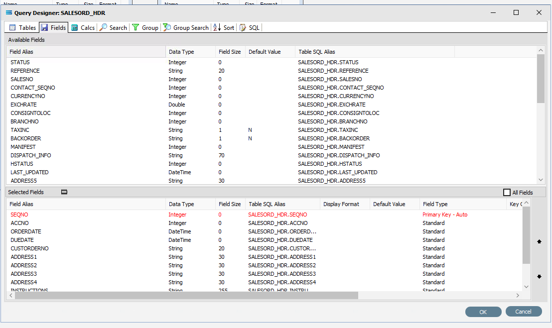
::: info
Selecting **Primary Key - Auto** identifies this field **SEQNO** as a field that will have its values automatically generated by the database server in the **SALESORD_HDR** dataset. This means that when a header record is written to **SALESORD_HDR**, a value will automatically be assigned to the **SEQNO** column/field. This **SEQNO** value is then written into the related line records into the **HDR_SEQNO** field in the **SALESORD_LINES** dataset, keeping the link between the two datasets accurate and well defined.
:::
8. Click on the empty **Key Generation** column for this field to see the pull-down list of available values. If the column does not seem to populate, make sure that you have selected **SEQNO** and that the column fields are bordered. Select SELECT SCOPE_IDENTITY(). This option should be at the top of the list.

9. Using this as the **Key Generation** means that the system will keep a track of the last identity value that was accessed by this particular session query. This keeps the child records correctly linked to the appropriate parent record.
::: info
If the column width default for Field Type and Key Generation are too small to see the full options, expand the columns as required with the mouse.
:::
10. Click **OK** at the bottom-right of the **Query Designer** to save the dataview and return to the definition canvas.
11. Now, either click the **Tables** tab on the **SALESORD_LINES linked to SALESORD_HDR** dataview, and in the **Query Designer** window click on the **Fields** tab. Or, click on the **Fields** tab on the same table.
12. In the **Selected Fields** pane, set the **Field Type** on the **HDR_SEQNO** field to **Foreign Key**. The **HDR_SEQNO** **Field Type** is set to **Foreign Key** because the field is related to **SEQNO** from the **SALESORD_HDR** dataset, and with this setting **Statelake** will automatically assign the **SALESORD_HDR SEQNO** value to this field.

13. Click **OK** at the bottom-right of the **Query Designer** to save the dataview and return to the definition canvas.
14. Close the definition canvas by selecting **Close** from the **File** menu. You will return to the **EXO: Sales Orders In** window.
15. Click **Save** to save and close the module.
The **DB Definition** named **EXO: Sales Orders In** will now appear in the structure tree under **Configuration > Components > Data Definitions > DB Definitions**.
## What To Do With The Data - Creating Maps
There have now been two definitions created for this tutorial – the **File Definition** called **Mitre10: Purchase Order**, and the **DB Definition** called **Exo: Sales Orders In**.
**Designer** will already be open. If not, open the **Statelake** module **Designer** for the selected configuration. An expanded structure tree is displayed on the left side of the screen.
### Create The Map
1. Follow the path **Configuration > Components > Maps**. Right‑click on **Maps** and choose **New** from the drop‑down list.
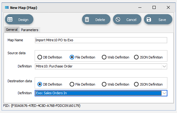
2. **New Map** will appear as an item on the tree. The **New Map** window contains two tabs - **General** and **Parameters**. The **Parameters** tab allows you to set other options, but for training purposes, we will be dealing with just the **General** tab. The following information is to be entered for the main map.
1. **Map Name** - this is the meaningful name that will identify the extraction process, and in this tutorial will be called **Import Mitre10 PO to Exo**.
2. **Source Data** – highlight the **File Definition** radio button.
3. **Definition** – the **File Definition** that was created for this configuration called **Mitre10: Purchase Order** can be selected from the pull-down list.
4. **Destination Data** – highlight the **DB Definition** radio button.
5. **Definition** – the name of the **DB Definition** that was created for this configuration called **EXO: Sales Orders In** can be selected from the pull-down list.
### Open The Map
1. Click the **Design** button in the top left of the window to open the map designer window **New** **Map**.
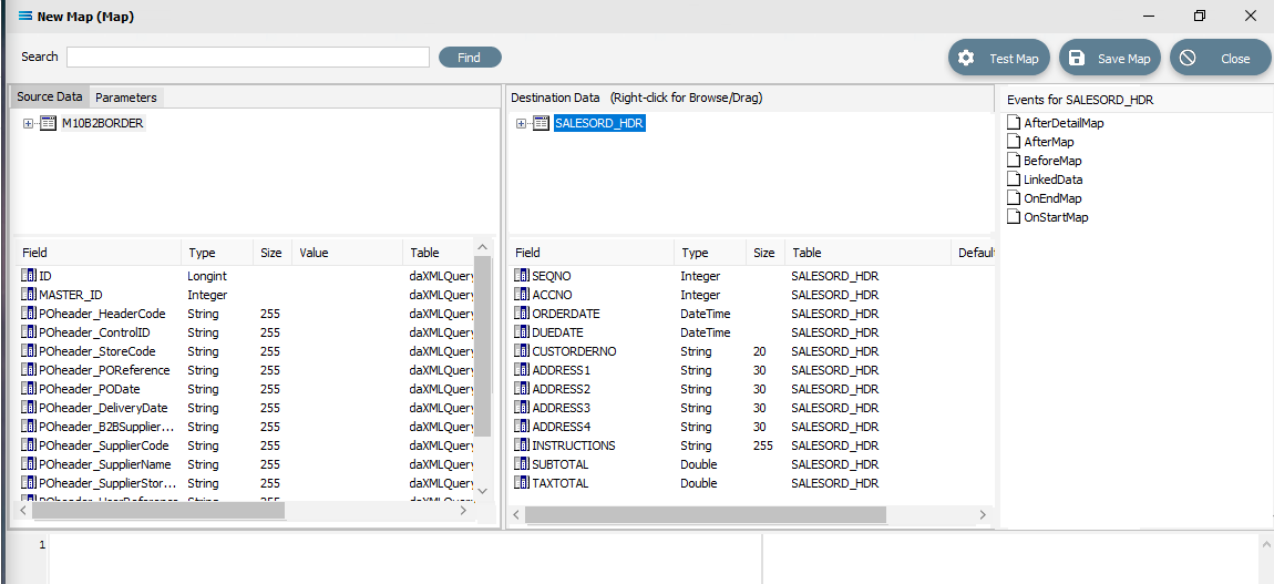
2. The **New Map** screen is split into five distinct panes beneath the search bar.
1. **Source** is split into two panes with **Source Data** and **Parameters** tabs. This is the definition of the source that data is to be read from.
2. **Destination Data** is also split into two panes. This is the definition that the data is to be written to.
3. **Field Events** on the right side of the screen. The events of the selected dataset or record.
4. **Scripting Area** beneath the **Source** and **Destination Data** panes. Where the script of each event is displayed and edited.
5. **Compiler Messages** below the **Scripting Area**. Messages that are returned by the compiler.
::: info
The first mapping operation is the linking of the datasets, to ensure that for every record in the source dataset there is a corresponding record in the destination dataset.
:::
3. In this tutorial we will link the source dataset table **M10B2BORDER** to the destination **SALESORD_HDR** dataset. **M10B2BORDER** is already showing in the **Source Data** pane, and **SALESORD_HDR** is already showing in the **Destination Data** pane.
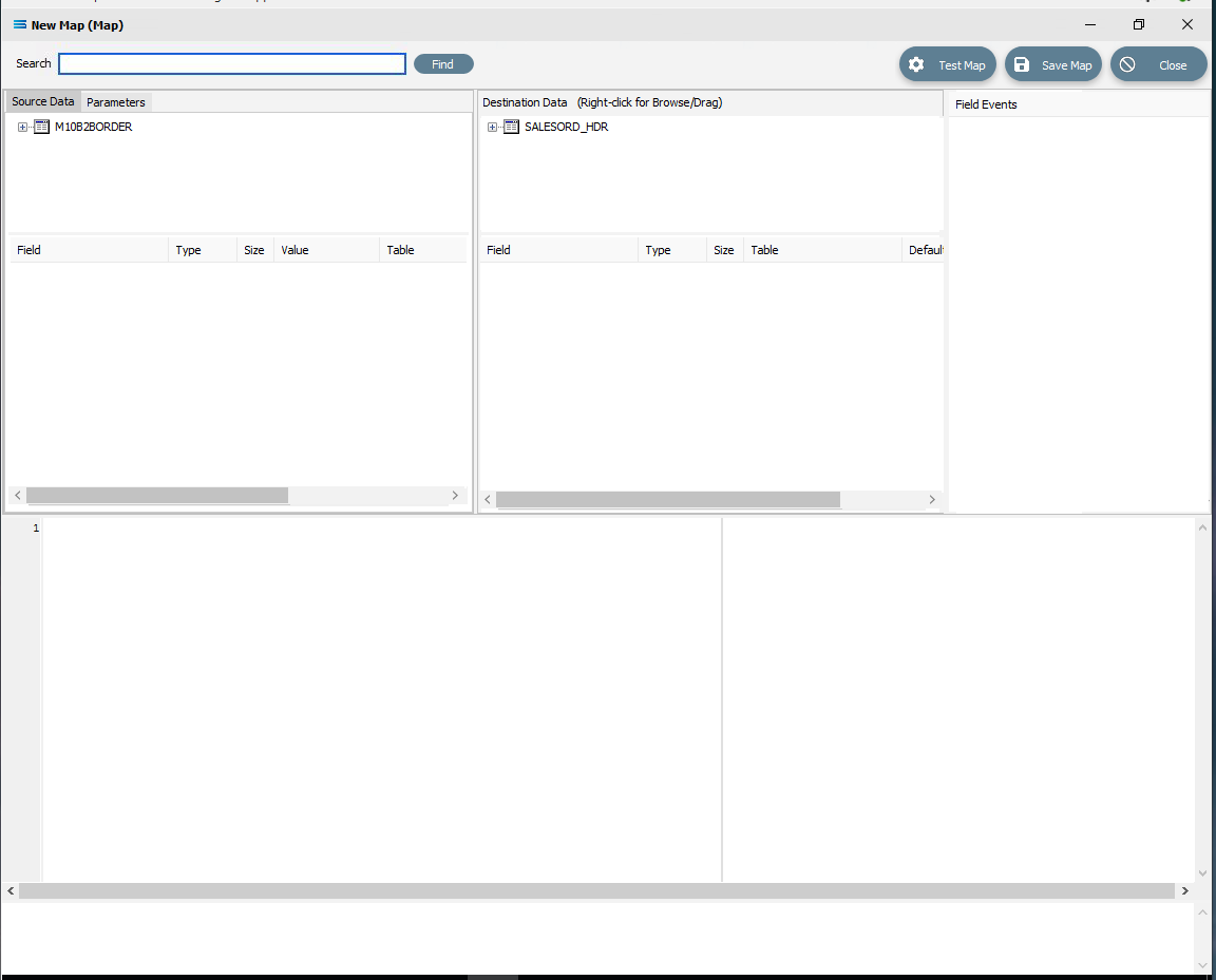
If you click on **M10B2BORDER** in the **Source** pane you will see the field names that are in the XML file appear in the lower part of the pane. Expand the pane if required.
If you click on **SALESORD_HDR** in the **Destination Data** pane, the fields in this dataset will appear in the lower part of the pane.
### Link The Datasets And Populate The Map
1. Link the two by dragging the XML **Root Node** called **M10B2BORDER** and dropping it onto the **SALESORD_HDR** dataset. You will see the established link appear in the **Scripting Area**, where the **LinkedDataEvent** code has been automatically generated.
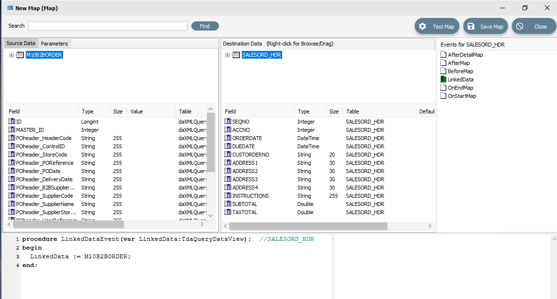
*Close up of the script.*
```pascal
procedure LinkedDataEvent(var LinkedData:TdaQueryDataView); // SALESORD_HDR
begin
LinkedData := M10B2BORDER;
end;
```
2. A list of events has also appeared in the **Field Events** pane, and this has been renamed to **Events For SALESORD_HDR**. The file icon beside the **LinkedData** event is now coloured **GREEN** which indicates a successful compilation for this event. If the icon was **RED**, this would indicate that the code was not successfully compiled.
3. Double-click on **M10B2BORDER** in the **Source Data** pane to display the linked node **PODETAIL**. Double‑click on **SALESORD_HDR** in the **Destination Data** pane to display the linked database table **SALESORD_LINES**.

4. Link these two by dragging the **PODETAIL** node and dropping it onto the **SALESORD_LINES** database table. You will see the established link appear in the **Scripting Area**, where the **LinkedDataEvent** code has been automatically generated.
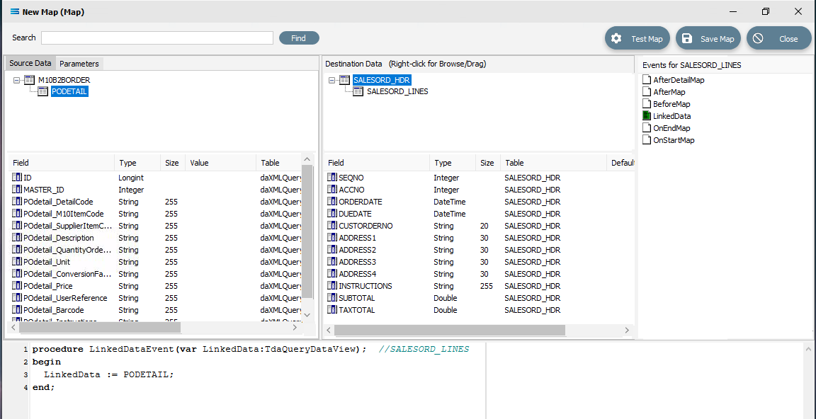
*Close up of the scripting.*
```pascal
procedure LinkedDataEvent(var LinkedData:TdaQueryDataView); // SALESORD_LINES
begin
LinkedData := PODETAIL;
end;
```
5. A list of events has also appeared in the **Field Events** pane, and this has been renamed to **Events For SALESORD_LINES**. The file icon beside the **LinkedData** event is now coloured **GREEN**.
### Link The fields
1. Click on **SALESORD_HDR** in the **Destination Data** pane. Then click on **ACCNO** in the **Field** list in the lower pane. Set the **ACCNO** field value manually to **1**. Do this by clicking anywhere in the **Scripting Area** panel and **Statelake** will generate code. Append to the third line and type **1** immediately after the Value :=.
*Close up of the script.*
```pascal
procedure OnMapEvent(var Value:variant); // ACCNO
begin
Value := 1
end;
```
2. When you click on another field name in the **Destination** pane, you will be prompted to save your changes. Click **Yes**.
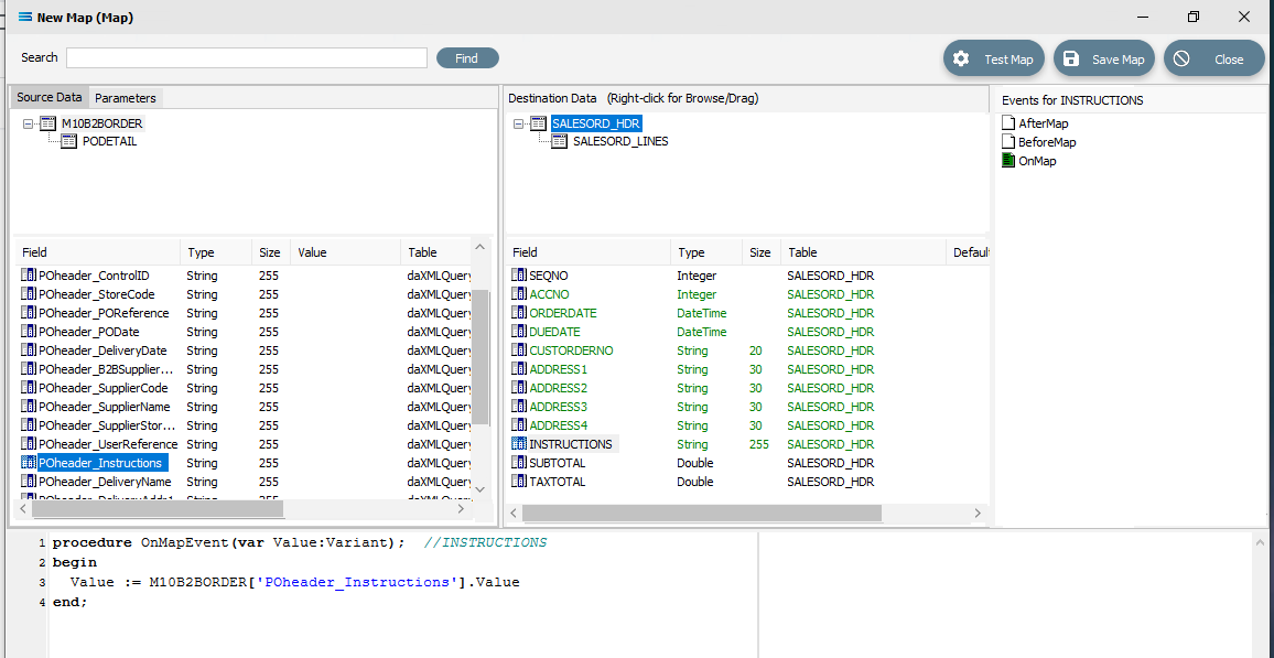
3. **ACCNO** has now changed to **GREEN**. Now link the fields using the same drag and drop technique used previously - drag the fields from the Source Data **M10B2BORDER** and drop onto the **Destination Data** field belonging to **SALESORD_HDR**, making sure that the destination field is highlighted before dropping the source field onto it, else the link will not be successfully established. Click on **M10B2BORDER** and **SALESORD_HDR** to bring up the correct series of fields, then drag and drop -
1. **POheader_PODate** to **ORDERDATE**
2. **POheader_DeliveryDate** to **DUEDATE**
3. **POheader_POReference** to **CUSTORDERNO**
4. **POheader_DeliveryName** to **ADDRESS1**
5. **POheader_DeliveryAddr1** to **ADDRESS2**
6. **POheader_DeliveryAddr2** to **ADDRESS3**
7. **POheader_DeliveryAddr3** to **ADDRESS4**
8. **POheader_Instructions** to **INSTRUCTIONS**
4. For each successful field drop, the colour of the field name in the **Destination Data** pane changes to **GREEN**, and an **OnMapEvent** procedure appears in the **Scripting Area**. In the **Field Events** pane, a set of events for each field has appeared, and each successful link is indicated by the **OnMap** event file icon being shown in **GREEN**.
5. The **SALESORD_HDR.SUBTOTAL** and **SALESORD_HDR.TAXTOTAL** fields are not populated through this drag-and-drop process. They need to be manually set to **0** (zero) as these totals are not given in the source file and need to be calculated. Click on the **SUBTOTAL** field in the lower destination pane, then click anywhere in the **Scripting Area** panel to generate the code. Append to the third line and type **0** (zero) immediately after the Value :=.
```pascal
procedure OnMapEvent(var Value:Variant); //SUBTOTAL
begin
Value := 0
end;
```
6. When you click out of the **Scripting Area** onto the **SALESORD_HDR.SUBTOTAL** field or another **SALESORD_HDR** field, you will be prompted to save your changes. Click **Yes**.
7. Now click on the **TAXTOTAL** field and repeat the process, appending a **0** (zero) to the Value := line.
```pascal
procedure OnMapEvent(var Value:Variant); //TAXTOTAL
begin
Value := 0
end;
```
8. And again, when you click out of the **Scripting Area** onto the **SALESORD_HDR.SUBTOTAL** field or another **SALESORD_HDR** field, you will be prompted to save your changes. Click **Yes**.
9. Now that the mapping of **SALESORD_HDR** is complete, the fields in **SALESORD_LINES** need to be mapped as well. Click on **PODETAIL** in the **Source Data** pane to bring up the associated fields in the lower **Source Data** pane, and then click on **SALESORD_LINES** in the upper **Destination Data** pane to bring up the relevant fields in the lower pane.
10. The value for **SALESORD_HDR .SEQNO** will be automatically generated by the **Statelake** process, and **SALESORD_LINES.HDR_SEQNO** is set as a **Foreign Key** in the **DB Definition**, so the value will be automatically populated from the linked related field from **SALESORD_HDR**.
11. The following remaining fields will be linked by the drag-and-drop process. Each successful drop will generate some script and the **Destination Data** pane field names will change to **GREEN**.
1. **POdetail_SupplierItemCode** to **STOCKCODE**
2. **POdetail_Description** to **DESCRIPTION**
3. **POdetail_QuantityOrdered** to **ORD_QUANT**
4. **POdetail_Price** to **UNITPRICE**
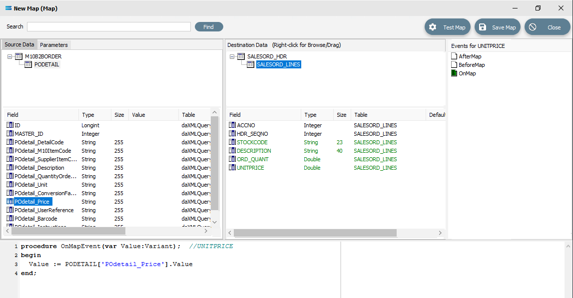
12. In the destination fields pane, click on **ORD_QUANT**, and change the end of line 3 of the script from .Value to .AsFloat to force a data type conversion.
```pascal
procedure OnMapEvent(var Value:Variant); //ORD_QUANT
begin
Value := PODETAIL['POdetail_QuantityOrdered'].AsFloat
end;
```
Then click on **SALESORD_LINES.UNITPRICE**, and you will be prompted to save your changes. Click **Yes**.
13. Now that **UNITPRICE** is selected, change the end of line 3 of the script from .Value to .AsFloat to force a data type conversion.
```pascal
procedure OnMapEvent(var Value:Variant); //UNITPRICE
begin
Value := PODETAIL['POdetail_Price'].AsFloat
end;
```
Click on another field such as **UNITPRICE**, and you will be prompted to save your changes. Click **Yes**.
### Create Detailed Scripts
1. Although the value for **SALESORD_LINES.ACCNO** is already specified on **SALESORD_HDR**, the mapping script for this field needs to be manually set. With the **SALESORD_LINES** dataset selected and its fields displayed, click on ACCNO. The digit **1** will appear in the Scripting Area.
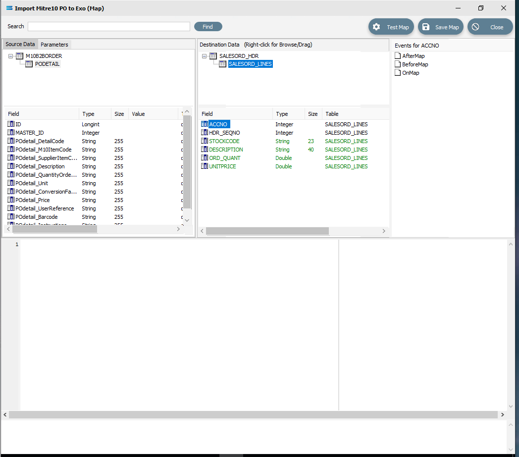
2. Click anywhere in the **Scripting Area** to generate the base code.
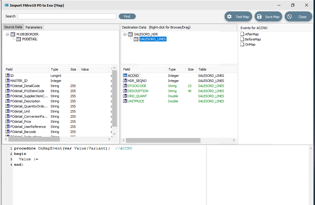
::: info
If this “empty” base code fails to generate and just the number 1 continues to be displayed, go to the **Events for ACCNO** pane in the top right of the window, and right-click on the **GREEN OnMap** icon - the icon itself, not the words **OnMap**. Select **Clear** from the pop-up. This will reset the script window so that you can try loading the base script again by clicking anywhere within the scripting window while **SALESORD_LINES.ACCNO** is selected in the destination pane.
:::
3. With this code still active, we need to swap over control to access the field name in **SALESORD_HDR**. To achieve this, follow these steps – be aware, it is easy to lose track of where you are!
4. The dataset **SALESORD_LINES** in the **Destination Data** pane should still be highlighted. RIGHT-click on **SALESORD_HDR** in the **Destination Data** pane to give control over to this dataset. You should get the cursor to change to a diagonally-barred circle. The relevant fields belong to this dataset will appear in the lower pane.
5. Now LEFT-click with your cursor in the blank space in the top right hand side of the top **Destination Data** pane. A right-click would usually copy and a left-click will normally paste. But as we are using this right‑click to simply swap datasets, the copy/paste is not required. You will see that the **Scripting Area** still displays the code that we generated for the **ACCNO** field in **SALESORD_LINES** - the code does not change.
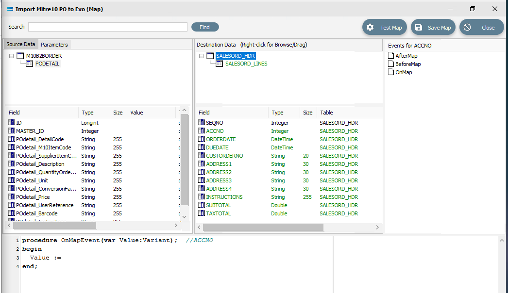
6. But now we do want to copy/paste, so RIGHT-click on **SALESORD_HDR.ACCNO** as is displayed in the lower portion of the **Destination Data** pane to copy the field name. You should get the cursor to change to a diagonally-barred circle beside **ACCNO**.
7. Then left-click with your cursor in the **Scripting Area** at the end of the 3rd line to append the field name to the Value := to post/append this code to the end of the line.
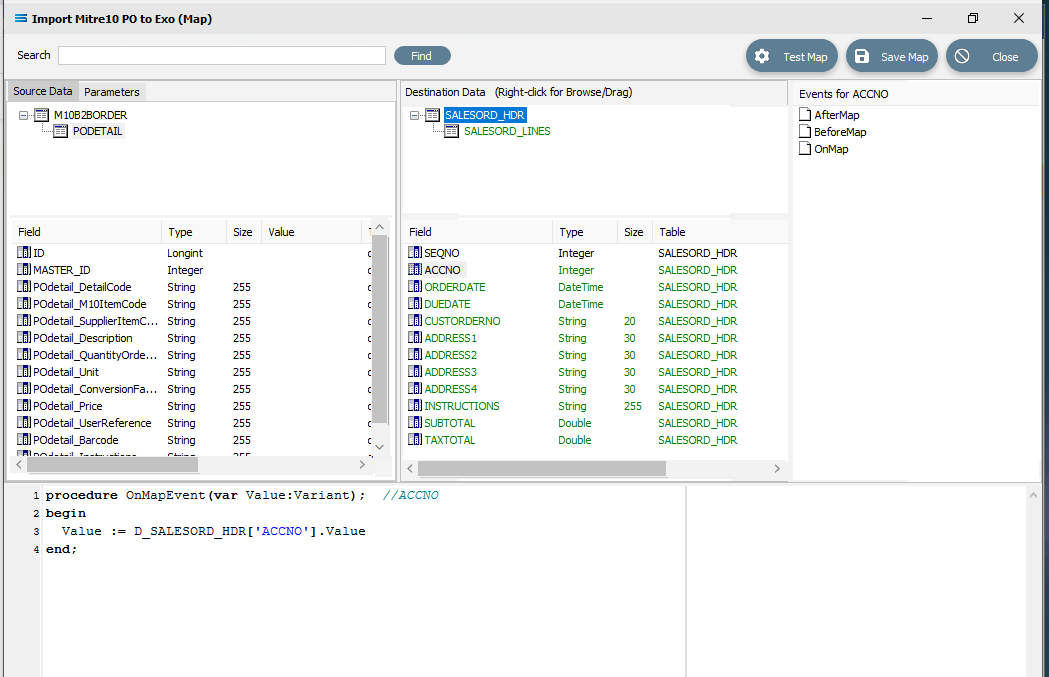
8. The code should now be as below. The D\_ denotes that the field is from a destination dataset. A close up of the code follows.
```pascal
procedure OnMapEvent(var Value:Variant); //ACCNO
begin
Value := D_SALESORD_HDR['ACCNO'].Value
end;
```
9. The line needs one further amendment. The .Value at the end of the line that you have just pasted, needs to be replaced by .AsInteger, so the code matches the example below.
```pascal
procedure OnMapEvent(var Value:Variant); //ACCNO
begin
Value := D_SALESORD_HDR['ACCNO'].AsInteger
end;
```
10. Click anywhere in the **Scripting Area** pane to select **Test Compile** and check that the code is correct.
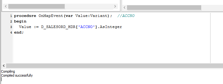
11. To verify that this code applies to **ACCNO** in **SALESORD_LINES**, click on the **SALESORD_LINES** dataset. You will be prompted to save your script changes – click **Yes**. Then click on the field **ACCNO**. This field should now display in **GREEN** and the compiler area should show that the code has been successfully compiled. If the compile fails, check your spelling and try again.
12. There are two fields in **SALESORD_HDR** that need further modifications to their script code. **ORDERDATE** and **DUEDATE** are presented as strings in the input/source dataset, but as the destination/output stores these valuesneed to be proper dates, so these strings need to be converted into the **DateTime** data type using the **StringToDateTime** function. Click on **SALESORD_HDR** to load the fields into the lower pane.
13. Click on **ORDERDATE** to display the **OnMapEvent** code in the **Scripting Area**. We want to change line 3 of the code from **Value := M10B2BORDER\['POheader_PODate'].Value** to the following code.
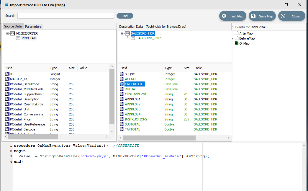
*Close up of the code follows.*
```pascal
procedure OnMapEvent(var Value:Variant); //ORDERDATE
begin
Value := StringToDateTime('dd-mmm-yyyy', M10B2BORDER['POheader_PODate'].AsString);
end;
```
14. When you click out of the **Scripting Area**, if you are prompted to save your changes, click **Yes**. This field should now display in **GREEN**.
::: info
To test your scripting to ensure that it holds no errors and will compile successfully, you can right-click in the blank space of the scripting area and select **Test Compile** from the list.
:::
15. Click on **DUEDATE** to display the code in the **Scripting Area**. Change line 3 in the script in the same manner, so as it reads as below.
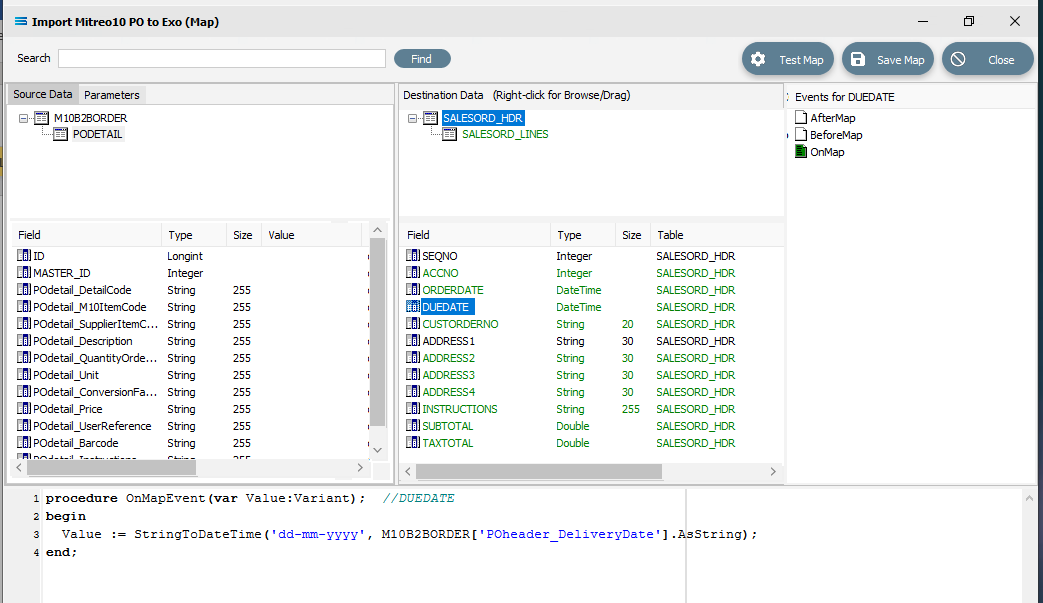
*Close up of the code below.*
```pascal
procedure OnMapEvent(var Value:Variant); //DUEDATE
begin
Value := StringToDateTime('dd-mmm-yyyy', M10B2BORDER['POheader_DeliveryDate’].AsString);
end;
```
16. When you click out of the **Scripting Area**, if you are prompted to save your changes, click **Yes**. This field should now display in **GREEN**.
::: info
Make sure that when you amend this code that you use the correct type of quote marks, else the script will not compile. The quote marks should be single and vertically straight such as '.
:::
17. To facilitate the orders totals mapping, a running order total calculation needs to be added as an **AfterMap** event on the **SALESORD_LINES** dataset. This introduces two new concepts: variables and logging. Firstly, the total for the current line is calculated and stored in the local variable **vLineValue**, which exists only within the event script. It is then added to the running total stored in the variable **Global1**, which is accessible in all event scripts in the **Map**. The results of the calculations from these two variables are output to the log.
18. Click on **SALESORD_LINES** to make that dataset the current active dataset. Click on the **AfterMap** icon in the **Events for SALESORD_LINES** pane. Click your cursor anywhere within the **Scripting Area**, and the following code should appear.
```pascal
procedure AfterMapEvent(var Value:Variant); //SALESORD_LINES
begin
// The AfterMap event will fire even for records that are skipped by setting Value:=False
// in the BeforeMap. To run AfterMap code only for records that were not skipped wrap your
// code with the following commented check
// if Value then
// Begin
//End;
Value :=
end;
```
19. Change the code to the following. If you prefer, you can leave the lines that are pre-fixed by two diagonal lines // because they are just comments. But for tidiness in this tutorial, they are removed or replaced.
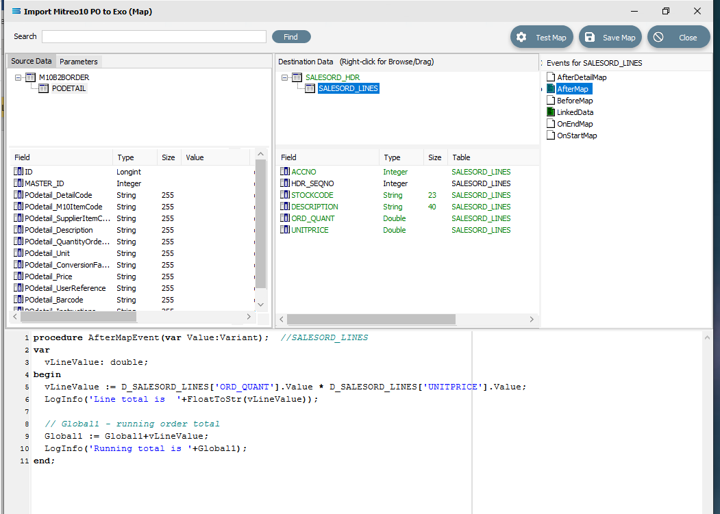
*Close up of the code is below.*
```pascal
procedure AfterMapEvent(var Value:Variant); //SALESORD_LINES
var
vLineValue: double;
begin
vLineValue := D_SALESORD_LINES['ORD_QUANT'].Value * D_SALESORD_LINES['UNITPRICE'].Value;
LogInfo('Line total is '+FloatToStr(vLineValue));
// Global1 – running order total
Global1 := Global1+vLineValue;
LogInfo('Running total is '+Global1);
end;
```
20. Make sure that your lines of code do not wrap onto a second line because this will affect the way that the script is read and processed. After entering the code as above, right-click in the **Scripting Area** and select **Test Compile** to verify that there are no errors and that the code has compiled successfully. Then click on another field name in the **Destination Data** pane, and if you are prompted to save your changes, click **Yes**. To see this code, click on the **AfterMap** icon in the **Events** for **SALESORD_LINES** pane.
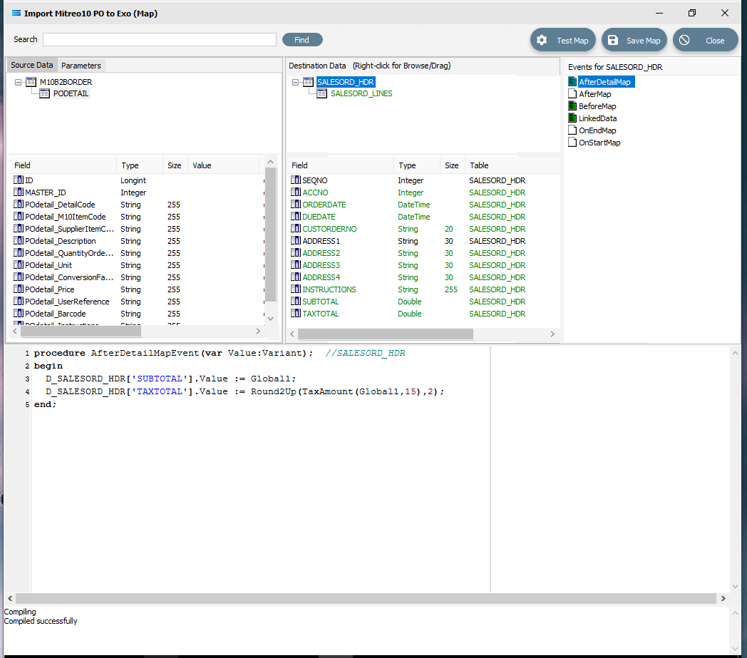
21. However, just having a total in the variable is not enough. It has to be assigned to a destination field. This is done in the **AfterDetailMap** event for the **SALESORD_HDR** dataset. Click on **SALESORD_HDR** to make that dataset the current active dataset. Click on the **AfterDetailMap** icon in the **Events** for **SALESORD_HDR** pane. Position your cursor in the **Scripting Area**, and the following code should appear.
```pascal
procedure AfterDetailMapEvent(var Value:Variant); //SALESORD_HDR
begin
Value :=
end;
```
22. Replace this code with the following to assign the values of the variables to the fields in the destination.
```pascal
procedure AfterDetailMapEvent(var Value:Variant); //SALESORD_HDR
begin
D_SALESORD_HDR['SUBTOTAL'].Value := Global1;
D_SALESORD_HDR['TAXTOTAL'].Value := Round2Up(TaxAmount(Global1,15),2);
end;
```
23. Again, you can **Test Compile** to error check your code. A successful compile will change the event icon to **GREEN**. Click on any field or node name in the **Destination Data** pane to save your script. Again, when prompted to save the script, reply **Yes**.
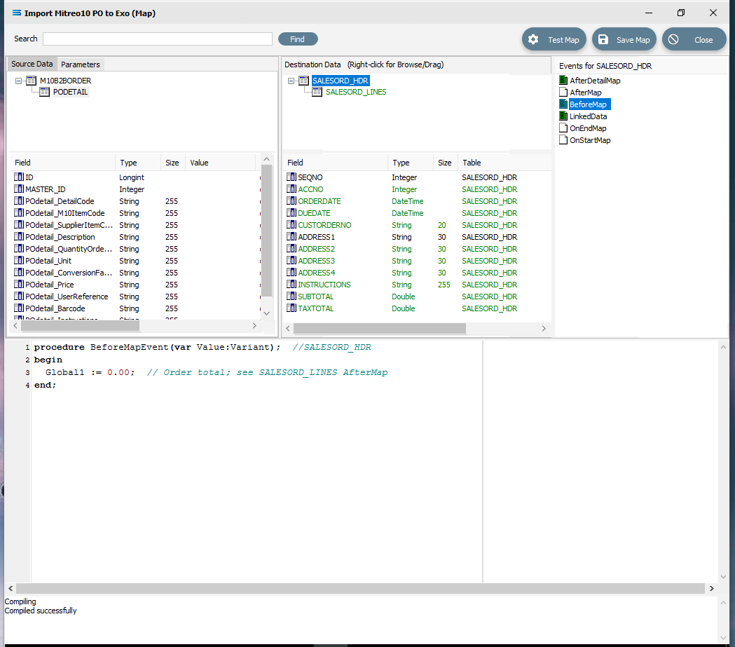
24. Finally, the running total variable **Global1** must be reset to zero for every order that is processed. To do this, code must be entered for a **BeforeMap** event in the **SALESORD_HDR** dataset. If not still selected, click on **SALESORD_HDR** to make the dataset the current active dataset. Click on the **BeforeMap** icon in the **Events** for **SALESORD_HDR** pane. Click into the **Scripting Area**, and replace the auto‑generated code with the following:
```pascal
procedure BeforeMapEvent(var Value:Variant); //SALESORD_HDR
begin
Global1 := 0.00; // Order total; see SALESORD_LINES AfterMap
end;
```
25. The comment after the 2 diagonal slashes on the 3rd line will be read only and will not be processed. Right-click while still in the **Scripting Area** to **Test Compile** to error check your code. A successful compile will change the event icon to **GREEN**. Click on any field or node/table name in the **Destination Data** pane to save your script. To check the code, you can click on the **BeforeMap** event icon for the **SALESORD_HDR** dataset.
26. The last field to be still lacking proper mapping is **ACCNO** in the order header table **SALESORD_HDR**. The order file does not include the account number from the system that we are importing into, so we need to determine what this number is, based on another key field. In this tutorial, this key field is called **POheader_StoreCode**. The EXO system into which the data is being imported, stores these codes against the debtor accounts in the **BRANCH** field. This next step will add the appropriate mapping to determine the value in **SALESORD_HDR.ACCNO**, and reject the order if the account cannot be found or identified. To make this action possible, additional code needs to be added to the **BeforeMap** event on **SALESORD_HDR** – including introduction of another global variable. Click on **SALESORD_HDR** to make the dataset the current active dataset.
27. Click on the **BeforeMap** icon in the **Events** for **SALESORD_HDR** pane. The code that you have just edited will display in the **Scripting Area**. Replace the code with the following code to make a query on the destination database, and then store the returned value in the variable **Global2**. Then the value of the variable is checked to determine whether to proceed with the order or reject it.
```pascal
procedure BeforeMapEvent(var Value:Variant); //SALESORD_HDR
var
vSQL, vErrStr, vInfoStr: string;
begin
Global1 := 0.00; // Order total; see SALESORD_LINES AfterMap
vSQL := 'SELECT ACCNO FROM DR_ACCS WHERE BRANCH =';
vSQL := vSQL + M10B2BORDER['POheader_StoreCode'].AsSql;
Global2 := GetSQLValueFromDest(vSQL,0);
if Global2 = null then
begin
vErrStr := 'Account not found for store code "';
vErrStr := vErrStr + M10B2BORDER['POheader_StoreCode'].AsString;
vErrStr := vErrStr + '".Order rejected.';
LogErrorAndContinue(vErrStr);
end
else
begin
vInfoStr := 'Store code "';
vInfoStr := vInfoStr + M10B2BORDER['POheader_StoreCode'].AsString;
vInfoStr := vInfoStr + '"matched to account no. "'+Global2+'".';
LogInfo(vInfoStr);
end;
end;
```
28. After entering the code as above, right-click and **Test Compile**. The message “**Compiling**” and “**Compiled successfully**” should appear on separate lines in the messages pane. Correct any error and re-test until the code is accepted.
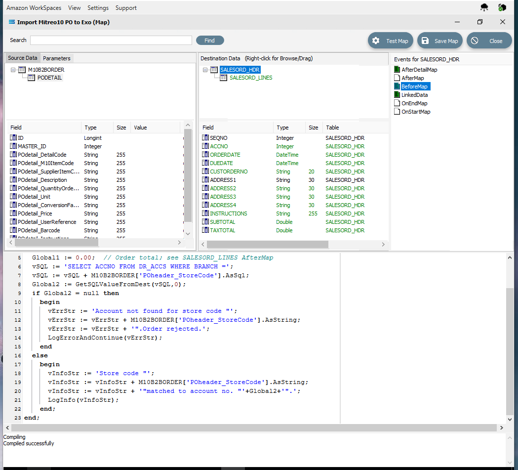
Then click on any field or table name in the **Destination Data** pane to save your script. Reply **Yes** to the prompt to save the script.
29. You are on the home straight. To complete the mapping, the value of the variable **Global2** needs to be assigned to **SALESORD_HDR.ACCNO**. Ensure that **SALESORD_HDR** is the current active table. Click on the field **ACCNO** from the lower **Destination Data** pane. Replace the code in the **Scripting Area** with the following:
```pascal
procedure OnMapEvent(var Value:Variant); //ACCNO
begin
Value := Global2; // Assigned in the BeforeMap
end;
```
30. The comment on the line will be ignored and not processed. Click on **SALESORD_HDR.ACCNO** in the **Destination Data** pane to save the script. Reply **Yes** when prompted to save the script.
31. Now save the **Map** and commit all of the mapping and scripting by clicking **Save Map** in the top right corner. Select **OK** to close the successful save message, then click on the **Close** button to close the map designer **Import Mitre10 PO to Exo** (Map) window.
32. To commit all the mapping and scripting, click **Save** to save and close the mapping module.
The **Map** named **Import Mitre10 PO to Exo** will now appear in the structure tree under **Configuration > Components > Maps**.
### Test The Map
Now test the **Map** to ensure it is working:
1. Open the **Maps** module again by clicking on **Import Mitre10 PO to Exo**, and click on the **Design** button.
2. The **Map Designer** screen called **Import Mitre10 PO to Exo** will display, with only the **Source** data **M10B2BORDER** showing, and **SALESORD_HDR** showing under **Destination Data**. **SALESORD_HDR** will be displayed in **GREEN**.
Make sure that the file specified in the **File Connection** called **Mitre10: Purchase Order** has been copied correctly and is available in the directory.
::: info
As a quick check, if the required file is not present in the selected directory then there will be no entries in the **Value** column of the **POdetail** table in the **Source** pane.
:::
3. Click **Test Map** in the top right corner of the screen, to execute the **Map** in memory and generate a processing log which is then presented in a preview pane. If there is no data selected, then the **Log** will have a pale **YELLOW** background. If this occurs check your definitions, change whatever is incorrect, and try the test again. Outright errors will have a dark **PINK** background, but with a successful test, the background will be pale **GREEN**. Examples of these log file colours are below.
*Example of no data - yellow log.*
*Example of an error - pink log.*
*Example of a successful process - green log.*
::: info
If you are testing the **Map** (or in due course running the associated **Action**) and encounter an error that produces a **PINK** Log file, make sure to carefully read the details about how the error was produced. This tutorial has one file that has intentionally been set up to fail, so depending on which file you are processing, this file may be the cause of the error. The error message that is generated in this case, was entered as part of a **BeforeMap** event on **SALESORD_HDR** starting at item #27 in the previous section.
:::
4. Close the pop-up preview of the log and the **DB Definition** window for **Exo: Sales Orders In** will be open.
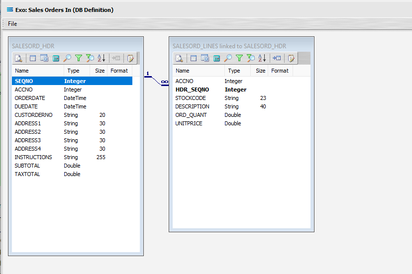
5. The query **SALESORD_HDR** and **SALESORD_LINES** linked to **SALESORD_HDR** will be displayed on the canvas. Click on the **Preview** button on **SALESORD_HDR** to view the processed records.
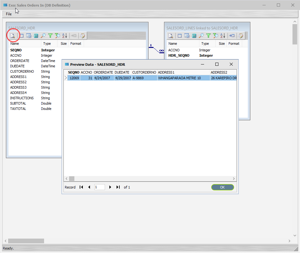
6. Using the **X** in the upper right corner, close the **Preview Data** pane, or click **OK**.
7. Click on the **Preview** button on **SALESORD_LINES** linked to **SALESORD_HDR** to view the processed records.
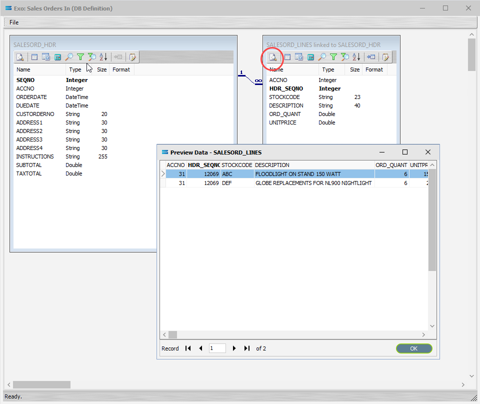
8. Using the **X** in the upper right corner, close the **Preview Data** pane, or click **OK**.
9. Select **File Close** on the canvas, the **Close** button on the **Map Designer** screen, and the **Cancel** button on the **Import Mitre10 PO to Exo** data entry window.
The **Map** has now been configured to insert records into a two-level table structure from a multi-tier XML source file. The links have been tested in memory to ensure that the **Map** has all the information required for a successful extraction.
However, no actual file to database activity has been generated.
The next step pulls all the configured components together to produce the destination tables.
## What Action To Take - Creating An Action
The final step is to pull all the definitions and configured components together to form an executable process to produce the destination database. This process is called an **Action**. While the details for an **Action** can be created manually, **Statelake** can also generate the **Action** quickly and easily for you.
**Designer** will already be open. If not, open the **Statelake** module **Designer** for the selected configuration called **Statelake_Training**. An expanded structure tree is displayed on the left side of the screen.
### Create The Action Automatically
1. Follow the path **Configuration > Components > Maps**. Right‑click on the **Map** you have just created **Import Mitre10 PO to Exo**, and choose **Create Action** from the drop‑down list. All the relevant components will be automatically added to this **Action**.
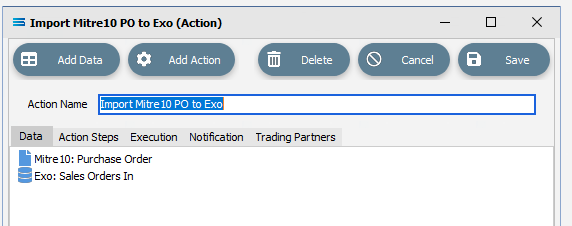
There is no need to do anything with this window, except select **Save** on the top right corner to close the module.
The **Action** named **Import Mitre10 PO to Exo** will now appear in the structure tree under **Configuration > Actions**.
### Run The Action
1. To run this **Action**, under the **Actions** directory, right-click on the **Import Mitre10 PO to Exo**, then select **Run Action** from the available options.
2. A window will pop-up showing the processing steps in a preview log, that will show the steps that were completed, how many records were extracted and processed, and where the destination file was saved. When the **Action** has been completed a status message will pop-up on screen indicating that processing is complete, and advising whether the process was successful or an error was encountered.
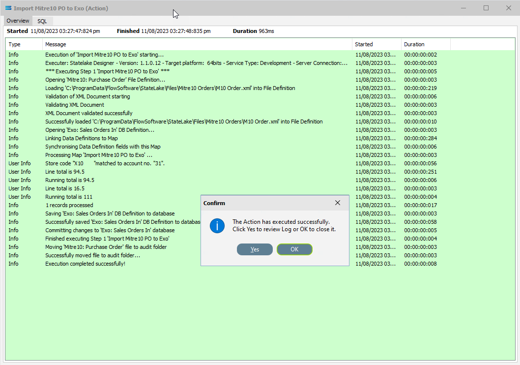
3. A successful **Action** will offer two choices – click **Yes** to review the log, or click **OK** to close the log without review. To close the **Log** after review, click the **X** in the upper right corner.
::: info
**Logs** can be re-opened at any stage, as many times as required. To review a **Log** from the **Manage Logs** window, double-click on the **Log** required. To drill into any line of the **Log**, double-click on the line to see more detail.
:::
4. The process is now complete, all modules have been closed, and the structure tree will be the only item on the **Designer** screen.
This **Action** will process a single file at a time. This is the default behaviour. The source location started with three (3) .xml files.
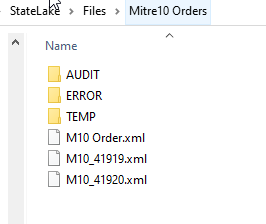
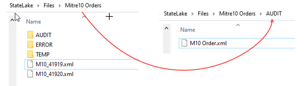
You will have seen from the **Log** that once this **Action** has 'been successfully processed, the file that was loaded and processed during the **Action** called file **M10 Order.xml** will have been moved into the **AUDIT** sub directory.

So it will no longer be located in its original sub-directory, as below. It has been moved from **Mitre10 Orders** to **AUDIT** so that it does not get re-processed.
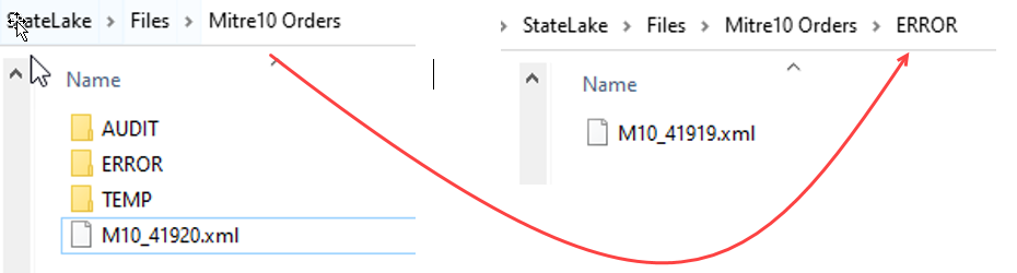
To process another file in the specified sub-directory whose name also fits the selection criteria, re-run the **Action** by right-click on the **Import Mitre10 PO to Exo**, then select **Run Action** from the available options. This time, the **Action** will encounter an error. This is by design.
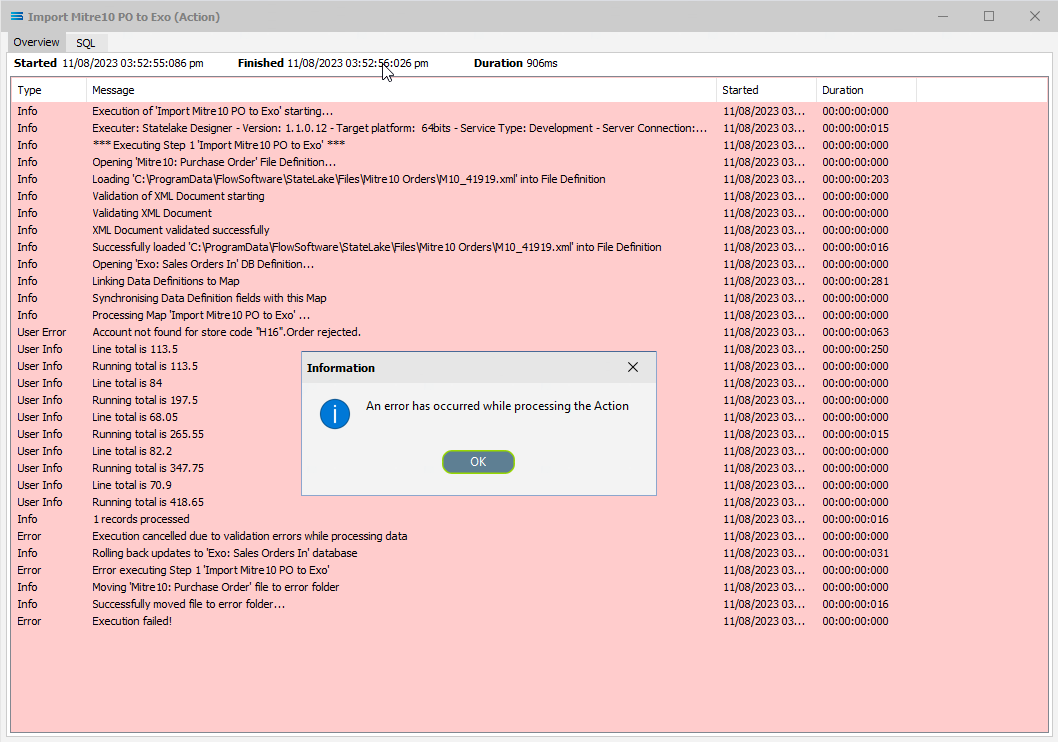
Because of this error, the file that was loaded and processed called **M10_41919.xml** has been removed from its original location and moved into the **ERROR** directory.
Click **OK** to close the dialog box and return to the **Log** window. Close this window using the **X** in the upper right corner.
Now run the **Action** again. This time, the file **M10_41920.xml** has been successfully processed.
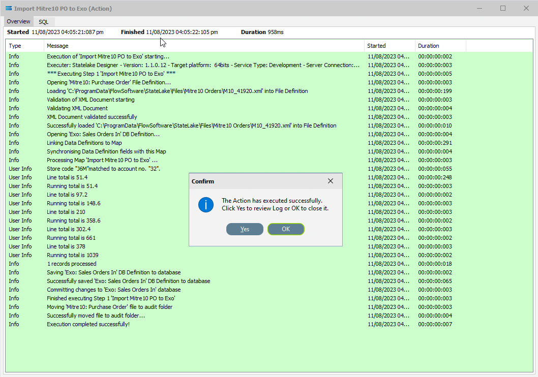
And subsequently moved from its original location into the **AUDIT** sub-directory, joining the initial file M10 Orders.xml. The original location of **Mitre10 Orders** now contains no files.
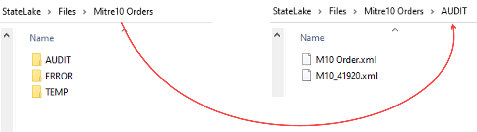
Close the **Log** window with OK.
Now, try running the **Action** one more time. This time the **Log** displays an unsuccessful completion - otherwise called an **Action** cancellation.
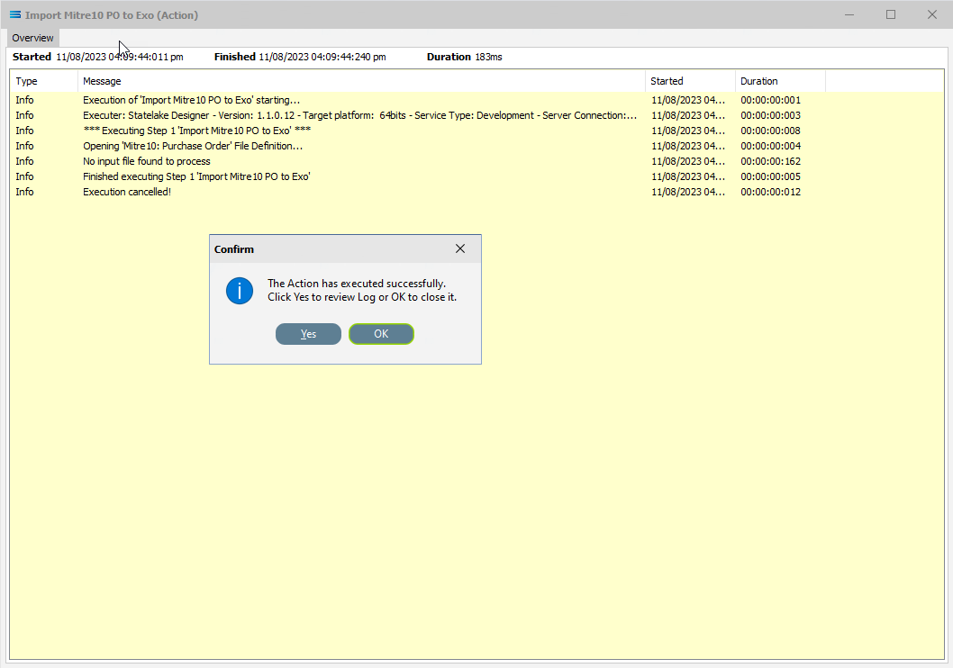
This is because there were no more files in the source location that met the selection criteria specified in the original location.
## Summary
Congratulations! You can breathe again - all the hard work is done for this tutorial. A two-level database table has now been generated from a multi-tier XML source file. And you have proven your skills as a fully-fledged scripting ninja.
In summary these are things that have been achieved for this configuration in this tutorial:
1. An XML file definition has been configured to enable reading of the XML file.
2. A database definition has been configured to enable writing into related database tables.
3. Various events have been introduced during mapping.
4. The use of variables in the mapping script.
5. Data conversion during scripting.
6. Querying databases from the map during processing.
## Quick Recap Quiz
This has been the biggest and most complicated tutorial so far, with much to take in. Here is a quick quiz to test your knowledge!
1. In which module would you find the Query Designer?
a. File Definition b. DB Definition c. Action
\2. How do XML files differ from flat files?
a. Contain extra information b. They are smaller c. Can be harder to read
\3. Which module allows you to transform source data to a different output format?
a. Action b. File Definition c. Map.
\4. Which event will be processed first?
a. AfterMap b. OnEndMap c. BeforeMap
\5. What does the acronym EDI stand for?
a. Electronic Data Interchange. b. Electronic Detail Input c. Eloise Does Indiana
\6. In the Query Designer, are you able to sort the names of the available fields?
a. Only in descending order b. Yes, fully c No, not at all
\7. In a database table, what does the foreign key link to?
a. A field in a different table b. An overseas database c. A record in a file
\8. What type of associate file does an XML file always need to have for a File Definition?
a. Executable b. Schema c. MS SQL
\9. Which type of variable allows a value to be used anywhere across a configuration?
a. Local global b. Script variable c. Super global
\10. This data segment is most likely to have come from which file type?
```xml
1
AnythingYouFancy
2
10
Sparkly
```
a. XML b. DAT c. CSV
## Next Steps
You are now becoming more familiar with the processes involved in manipulating your data, and more familiar with the ease with which files and databases are handled by **Statelake**.
The last step on this journey brings together all of the things you have learnt so far, and introduces some new and exciting functions:
* **Tutorial 4 - Extracting XML Invoices Out Of A Database**
* **Tutorial 5 - Statelake Magic SQL**
* **Tutorial 6 - Import CSV Purchase Orders Into A Database**
* **Tutorial 7 - Exporting And Importing Configuration Data**
::: details Quick recap quiz answers
1. b 2. a 3. c 4. c 5. a 6. b 7. a 8. b 9. c 10. a
:::
Congratulations on your progress!