Tutorial 1: Exporting Creditor Accounts Into A Flat File Supplier List
Before starting this tutorial, the sample training files must have been copied to your computer, and the configuration DB Statelake_Training must have been created in Statelake.
This tutorial illustrates the simplest process of extraction of data from a database into a file using Statelake, by exporting creditor accounts into a flat file supplier list. There may be many reasons for data to be extracted and produced into a simpler file format, such as when a list of accounts needs to be shared either within the organisation or with external parties. The resulting file will be a .CSV file.
Each step should be fully completed before processing to the next. The topics covered are:
Creating database connections
Create a file connection
Create a database definition for extraction with a single dataset
Create a flat file definition with a single dataset
Create a basic one-to-one map
Create a basic action with one map action step
In this tutorial, a sample company has several branches that each have a stand-alone computer system with no access to any shared files or data. The only means of updating their data is to import the information into their existing systems from a file.
To successfully achieve this, there are a number of things that need to be taken into consideration or decided on, before the process is started.
Where the data is.
The location of the database that we need to access, and how to connect to it.
The location for the destination file to be saved, and what it is to be named.
What the data is.
What query we need to run against the database to get the data we need.
How the file is going to be structured.
What fields will this file have.
What is the field type (number, alpha, alpha-numeric, date etc.)
What size are the fields etc.
What to do with the data.
Which database fields are going to be mapped to which fields in the flat file.
What action needs to be taken to start the process.
Opening The New Configuration
Statelake Manager should be open.
If Config Databases is not still selected, select it now. The new configuration Statelake_Training that you have just set up will appear in the list pane on the right‑hand side of the window.
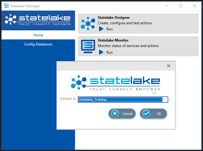
Click on Home above Config Databases. Run Designer by clicking on the Run button.
Connect To - select the newly created configuration from the pull-down list. For the purposes of this tutorial select Statelake_Training from the pull-down list. Click OK.
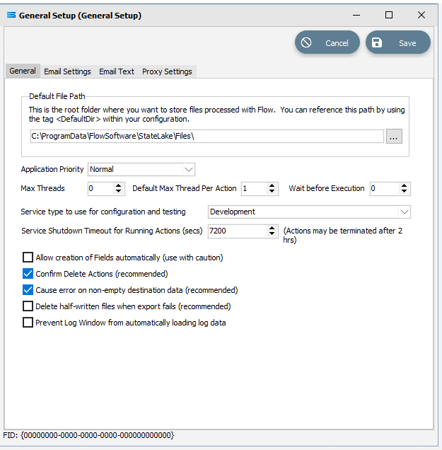
As soon as the configuration opens in the Designer master canvas for the first time, the General Setup window automatically opens. This window presents a series of tabs – General, Email Settings, Email Text, and Proxy Settings. The Default File Path is C:ProgramData\FlowSoftware\Statelake\Files. This General Setup can be viewed at any time by selecting Global Setup > Generel Setup on the structure tree. For the purposes of this tutorial, accept the default values and click Save.
You will now be in the main screen with a blank Designer canvas and the menu tree on the left.
Where The Data Is - Creating Database Connections
Pivotal to the successful implementation of this Statelake configuration, is the creation of the database (DB) connection. For the purposes of this tutorial, DB Connection is the Statelake module under the Data Connections umbrella that is used to identify the specific database that contains the source data, and where that database is located. In this tutorial we will create a DB Connection to the source EXO database Data_Demo that holds the suppliers’ data, and that was previously restored.
An expanded structure tree is displayed on the left side of the screen.
Create DB Connection
Follow the path Configuration > Components > Data Connections > DB Connections. Click on DB Connections and once DB Connections is expanded, you will see a connection called _Self. Right‑click on DB Connections and choose New from the drop-down list.
New DB Connection appears as an entry under DB Connections. In the New DB Connection window the following information is to be entered.
Connection Name – some source databases will have obscure or convoluted names. This field is the user-friendly identifier name that will appear in the Statelake configuration and references the source database. Enter MYOB Exo. The two tick boxes Use Config Database and Use Config Database Server Only should be left blank.
The lower screen is then split into two tabs - General and Advanced. The Advanced tab allows you to set other options, but for training purposes, we will be dealing with just the General tab.
Connection Type – select the database engine that is to be used. Since the configuration Statelake_Training has been up using Microsoft SQL Server, ensure that the radio button Microsoft SQL Server is selected.
Server Name – the server location for the source database. Enter the server name – the name that was used to log on to either Microsoft SQL Server Management Studio.
Database Name – the name of the database. Enter Data_Demo.
User Name and Password – fill these out with SQL authentication details or leave them blank to use Windows Authentication.
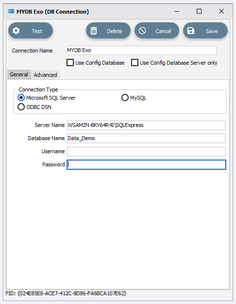
Click on the Test button in the top left of the window when all details are populated. If the details are all correct, you will be presented with a message “Connection Test Successful”. Click Ok to proceed. If the test is unsuccessful, you will see the error reported by the database server. Correct any errors as required.
It is impossible to cover all possible errors that may come from a database connection because any error is specific to the type of the database it comes from, and each database type may have hundreds of errors that can be generated. If you are unsure of what the error is, then try searching the web for documentation about the errors for the type of database you are attempting to connect to.
If the connection test is successful, click Save to save and close the connection module.
Along with an automatically generated DB Connection named _Self, the DB Connection named MYOB Exo will now appear in the structure tree under Configuration > Components > Data Connections > DB Connections.
Where The Data Is - Creating File Connections
Also under the Data Connections umbrella, the File Connections module is somewhat similar to DB Connections. But where DB Connections in this tutorial details information relating only to the source database, File Connections is a configuration module that points to a specified file directory that will hold the output or destination file. In this tutorial, the output file will be the flat file suppliers list.
Designer will already be open. If not, open the Statelake module Designer for your selected configuration. An expanded structure tree is displayed on the left side of the screen.
Create File Connection
Follow the path Configuration > Components > Data Connections > File Connections. Right‑click on File Connections and choose New from the drop-down list.
New File Connection appears as an entry under File Connections. In the New File Connection window the following information is to be entered.
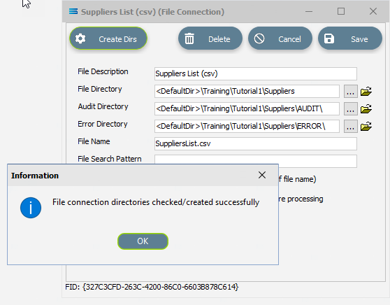
File Description – the name that is meaningful and best describes the output file. For this tutorial it will be Suppliers List (csv), meaning that it is a .CSV file containing a list of suppliers. Enter this name into the File Description field.
File Directory – the directory location of the output file. Enter <DefaultDir>\Training\Tutorial1\Suppliers.
The <DefaultDir> tag refers to the default file path already set-up within the Statelake General Setup, under Global Setup. C:\ProgramData\FlowSoftware\Statelake\Files will be the path referenced by this <DefaultDir> tag.
c. Audit Directory – will be automatically populated when you tab into it.
d. Error Directory – will be automatically populated when you tab into the Audit Directory.
Statelake uses two sub-directories to manage files - AUDIT and ERROR. When a file is successfully processed in, or successfully sent after being written out, it is moved into the AUDIT directory. If an error occurs during file processing, the file is moved into the ERROR directory.
e. File Name – the actual name of the output file. In this tutorial, it will be SuppliersList.csv.
f. File Search Pattern - leave this field blank. It is used by Statelake when files are being read.
g. Ensure Unique File Name – if this box is ticked, a number will be added to the end of the file name to ensure that the file name will be unique and will not overwrite a file already in the output folder. In this tutorial, this box will be left unticked.
h. Allow This File To Be Accessed – for this tutorial leave unticked.
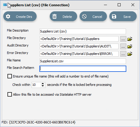
If the sub-directories you have specified do not yet exist or you are not sure whether they exist, you will need to check by clicking on the button Create Dirs which is located on the top left of the window. If they do not exist, they will be created, else they will be confirmed as current and available by display of the pop-up message “File connection directories checked/created successfully”. Click OK to close this pop-up window.
Click Save when all details are entered correctly, to save and close the module.
The unit named New File Connection will change on Save to Suppliers List (csv) in the structure tree under Configuration > Components > Data Connections > File Connections.
What The Data Is - Creating DB Definitions
Once the data source and destination locations have been specified, Statelake needs to know what the data is so that the proper fields can be accessed and the data correctly either extracted from the database, or written to the database. For this tutorial, this means defining the exact information to be extracted to populate the flat file suppliers list, and also identifying how the output file is to be constructed. Sitting under the Data Definitions umbrella, Statelake uses the DB Definitions module to define these data structure components, and to design the database queries for both reading the data out of, and writing in to, the databases. There are a few differences between the extraction of these DB definitions and the importing of DB definitions.
In this tutorial we will use a database definition to extract the creditors records, by querying the Exo database, previously identified via the DB Connection module as MYOB Exo. While extraction is possible accessing multiple tables from a database, this tutorial deals with extraction from a single table only.
Designer will already be open. If not, open the Statelake module Designer for the Statelake_Training configuration. An expanded structure tree is displayed on the left side of the screen.
Create DB Definition
Follow the path Configuration > Components > Data Definitions > DB Definitions. Right‑click on DB Definitions and choose New from the drop-down list.
New DB Definition appears as an entry under DB Definitions. In the New DB Definition window the following information is to be entered.
DB Definition Name – the name that is meaningful and best describes the query/extraction. We will use Exo: Creditors Out.
DB Connections – this is the name of the source database, identified by the meaningful name that was given in the DB Connections module. Right-click anywhere in the empty box to see the Add pop-up. Follow the arrow to see a display list of all the found connections. _Self will display. Select the one you want from the list – in this tutorial, it will be MYOB Exo.
If you select an incorrect source in error, simply double-click the name in the DB Connections box to de-select it.
c. Transaction Identification – leave with the defaults as set.
d. Duplicate Record Handling – leave with the defaults as set.
e. Disable Automatic String Trim – this will be ticked. Leave with the default as set.
f. Save Null Fields as Blank Strings – leave with the default as set.
g. Disable SQL Transactions – leave with the default as set.
h. Save Blank String Fields as Nulls – leave with the default as set.
i. Include Null Values in SQL statement – leave with the default as set.

Click Design in the top left of the window.
Create DB Dataview Query
A blank definition designer canvas will display. To start creating your query, click on the File menu in the top left corner, and choose New (or use the Ctrl+N).
The New Items window will open and only one item called DB Dataview will be displayed and highlighted. If it is not already selected, click on the DB Dataview icon to highlight it, then click OK to add a DB Dataview.
The Query Designer window will open. There are 8 tabs in this window.
The first tab in the Query Designer is Tables. The upper pane contains a list of available tables, and the lower pane will display selected tables. The separator bar between the panes can be raised or lowered as required. Scroll down the available tables to CR_ACCS (Creditor Accounts) and double-click to select it. The table will remain visible in the upper pane but will also appear in the lower pane.
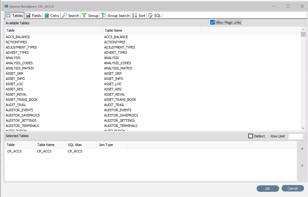
This is an alphabetic list but you may have to expand the window height to see all the entries.
Now move to the Fields tab, and add the following fields to query by double-clicking on them: As each one is selected, it will disappear from the upper pane and appear in the lower pane. If you make a mistake and select the wrong field, then simply double-click on it in the lower pane and it will de-select and reappear in the upper pane.
ACCNO (account number)
NAME (account name)
ADDRESS1
ADDRESS2
ADDRESS3
PHONE
FAX
EMAIL
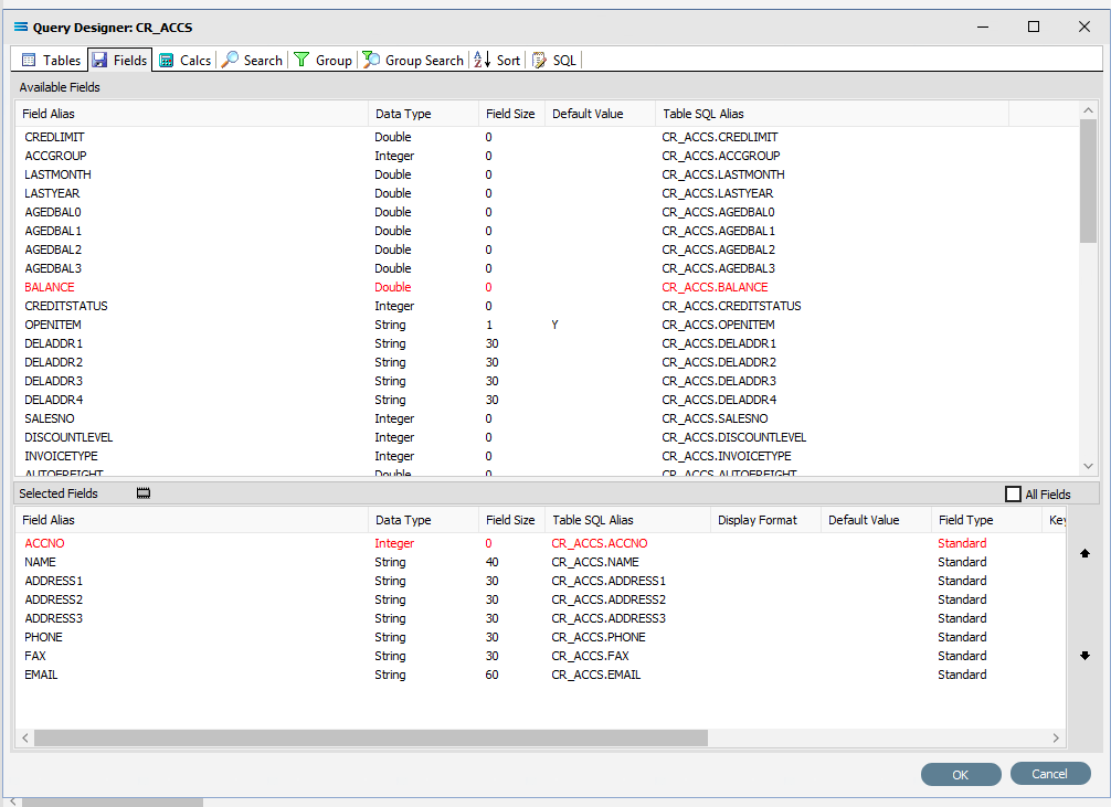
The fields are colour-coded in the Query Designer. RED indicates that the field is either calculated or is an automatically generated identity, such as ACCNO and BALANCE. PINK indicates that the field does not allow nulls.
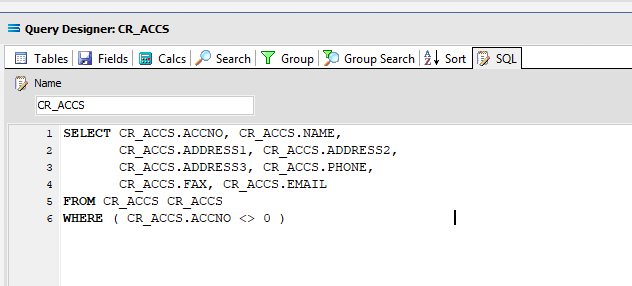
Click on the SQL tab to see the SQL query that has been generated. It lists all of the fields you selected and the table they are to be retrieved from. You will see that each field is prefixed with the table name with a full-stop as a separator.
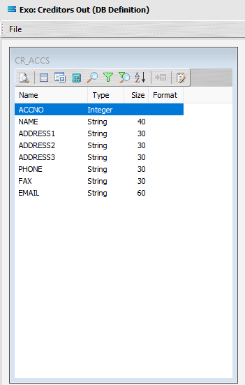
Click OK at the bottom-right of the Query Designer to save the dataview and return to the definition canvas. The configured dataview will display as a window on the canvas with the title CR_ACCS, listing all of the selected fields. Expand this window as required.
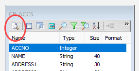
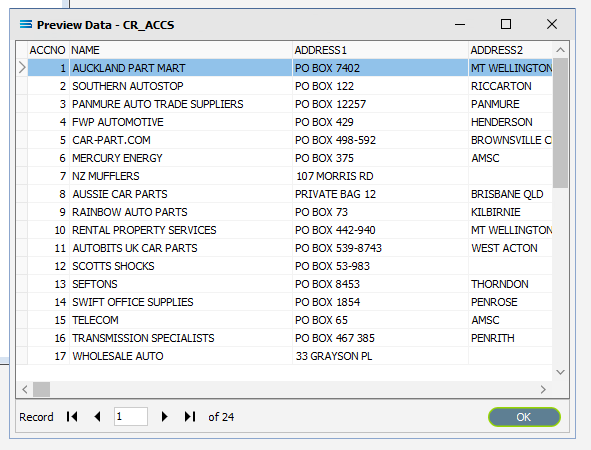
Click on the Preview button (the first tab that has a magnifying glass) to run the query and see the results.
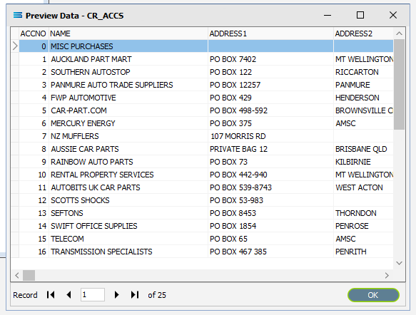
These results will open in a specific window called Preview Data – CR_ACCS. The first item in the results is a MISC PURCHASES account (account number 0), and as it does not represent a specific creditor, it should be excluded from the query so as to be excluded from the suppliers listing that will be produced.
Click OK at the bottom of the preview window to return to the definition canvas and the open dataview CR_ACCS.
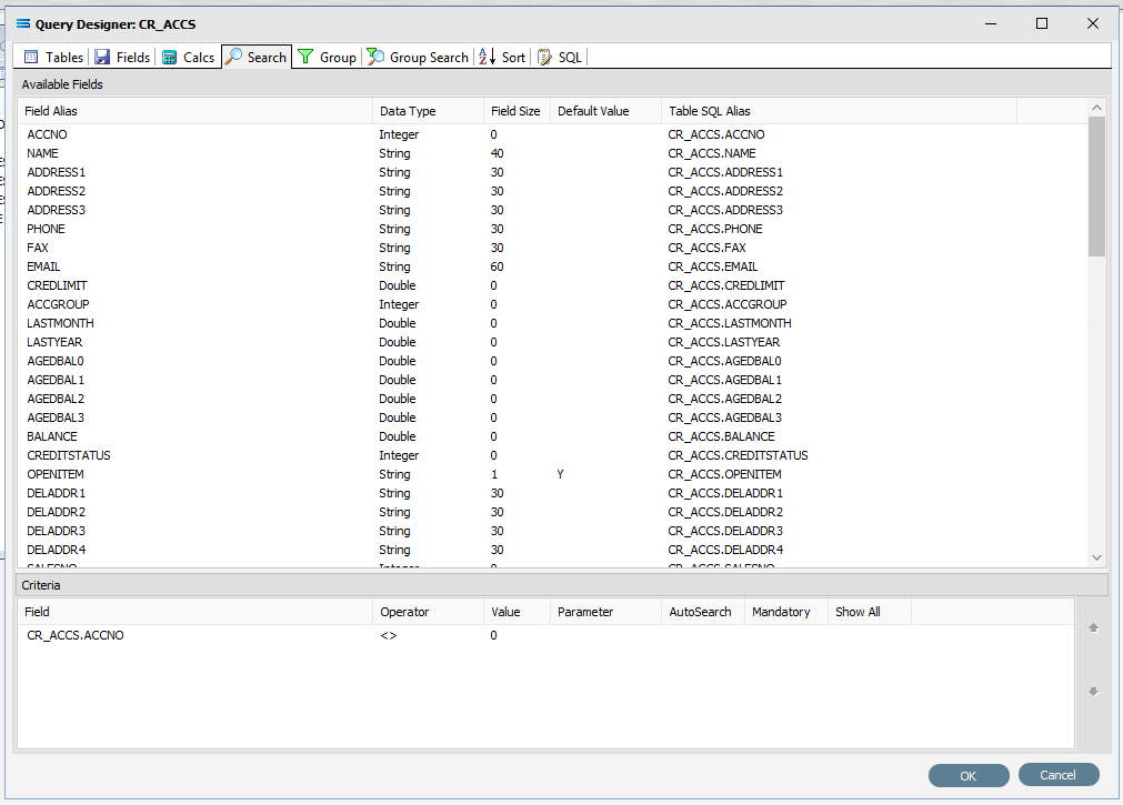
Now click on the Search button (the single magnifier) to open the Query Designer and the Search tab. The window will have the two panes. To exclude account 0 (MISC PURCHASES) from the query, double-click on the ACCNO field in the upper pane to pull it into the lower pane as selected field. The field will stay displayed in the upper pane, but will appear as CR_ACCS.ACCNO in the lower pane. Click into the Operator field on the selected line in the lower pane, and select the not-equal-to operator <> from the drop-down list. Enter 0 (zero) into the Value field and tab to exit. This will now exclude an entry with an account number of zero (0) from the query.
Since this is our only condition, click OK at the bottom of the window.
Preview Your Results
You can click on the Preview button again to run the query and see the results in the Preview Data – CR_ACCS window. The MISC PURCHASES account (0) should no longer appear.
Click OK to close.
Close the definition canvas once you are satisfied that you are extracting the correct records in the query by selecting Close from the File menu. You will return to the DB Definition window. Click Save to save and close the module.
The DB Definition named Exo: Creditors Out will now appear in the structure tree under Configuration > Components > Data Definitions > DB Definitions.
What The Data Is - Creating File Definitions
The File Definitions module is used to design the structure of the files that are read from, or written to, the Statelake configuration. There are three types of files that can be specified in this module: “flat” text files, XML files, EXCEL (binary), and EDI (EDIFACT) type files.
EDIFACT is an acronym that stands for Electronic Data Interchange For Administration, Commerce and Transport. It is a more specialised file type with rules ratified by the U.N., that is used in global data transfer. This file type will not be used in this tutorial, but will be examined in a later tutorial.
In this tutorial a flat file definition for the suppliers list .CSV destination file will be created.
Designer will already be open. If not, open the Statelake module Designer for the selected configuration. An expanded structure tree is displayed on the left side of the screen.
Create File Definition
Follow the path Configuration > Components > Data Definitions > File Definitions. Right‑click on File Definitions and choose New from the drop-down list.
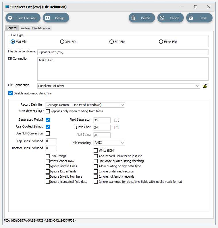
New File Definition appears as an entry under File Definitions. In the New File Definition window under the General tab, the following information is to be entered.
File Type – leave the selection as Flat File.
File Definition Name – enter the definition name of the destination file, as specified during the creation of the File Connection. In this tutorial it is Suppliers List (csv).
DB Connection – right-click anywhere in the empty DB Connection box to see the Add pop-up, and a list of all the found connections will be displayed. Select the one you want from the list – as with the DB Definition, _Self will display, along with MYOB Exo. A source database is required to be selected for all definitions - select MYOB Exo.
File Connection - select Suppliers List (csv) from the pull-down list.
Disable Automatic String trim – this is ticked. Leave with the default tick as set.
Record Delimiter – leave as set, as Carriage Return + Line Feed (Windows).
Auto-detect CR/LF – this applies only when files are being read. As we are creating a file to write in to, this is box is not ticked.
Separated Fields? – tick the box to separate the fields, and the Field Separator field will populate as 44 and comma [ , ]. Leave as ticked.
Use Quoted Strings – tick the box to activate, and the Quote Char field will populate as 34 and quote [ “ ]. Leave as ticked.
All other fields and tick boxes are to be left as set.
Click Design in the top of the window.
Create File Dataview Query
A blank definition designer canvas will display. To start creating your file, click on the File menu in the top left corner, and choose New (or use the Ctrl+N).
The New Items window will open and only two items called File Dataview and DB Dataview will be displayed. File Dataview should be selected - if not, select File Dataview and click OK to add a new File Dataview. The File Designer window will open.
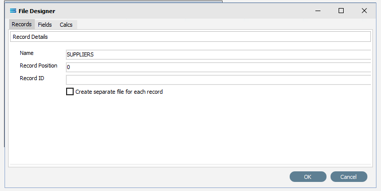
Unlike Query Designer, all records and fields in File Designer are entered manually when creating a flat text file. The first tab of 3 is Records, and the section Record Details.
Name – an alphanumeric field, this is the name given to this record. It will be referred to throughout the Statelake configuration for mapping purposes. This name will also prefix the column names when printed. In this tutorial the record Name is SUPPLIERS.
Statelake forces all records and field names to be entered as uppercase for consistency across all definitions.
b. Record Position – this is a numeric integer value that is used to manage the sequencing of records at the same level within the file. For this tutorial use 0 (zero).
c. Record ID – an alphanumeric field that accepts both upper and lower case. Record ID is to be left blank for this tutorial.
d. Create separate file for each record – we want only one supplier record file so leave this box unticked.
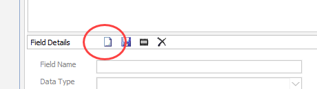
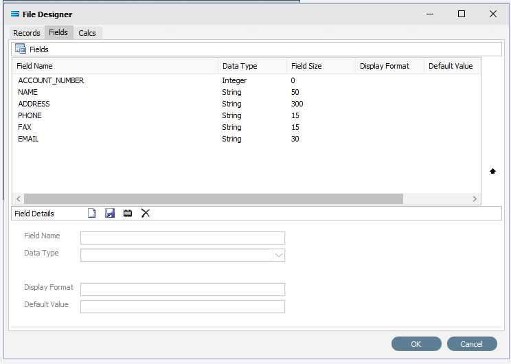
The next tab is Fields. The window is split into two panes. The upper pane Fields shows the fields as they are created, while the fields themselves are created in the lower pane Field Details. In the lower pane. click the Add Field icon (1st icon, blank page) to create a field.
Tab to move between fields. These steps are to be repeated for all the fields listed below.
a. Field Name – a meaningful name to describe the contents of this field. The first field name is ACCOUNT_NUMBER. Input is forced to uppercase.
Be consistent with your naming conventions. Decide on the use of a separator such as a hyphen ( - ) or an underscore ( _ ) to split multiple word record or field names, rather than use a space. It is best to try not to deviate from whichever convention you decide to use.
b. Data Type – from the pull-down list select the record type. ACCOUNT_NUMBER will be an Integer, although other types including boolean and string are able to be selected as required.
Although on the initial settings screen for this File Definition, the field Separated Fields? was ticked, Field Size may be requested for some data types only - such as with a string. If required, the default is zero (0) and an integer value is expected.
c. Display Format – the format of the data and how it is to be displayed. Particularly useful where numbers or dates have been selected as the Data Type. Unless specified, leave blank.
d. Default Value – a default value for the field, such as populating the field with M for a tax code field. Unless otherwise specified, leave blank.
Click the Save icon (floppy disk) to save the field.
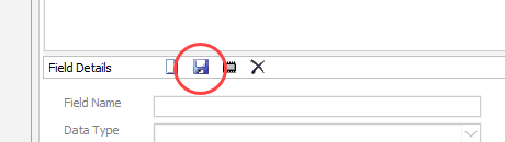
The field and details appears in the upper pane.
If you accidentally click OK rather than Save and are returned to the File Designer screen, simply tab across to the Fields tab (3rd tab), and continue where you left off.
Repeat creating fields as per 4 and 5 above to create all the additional required fields as listed below -
NAME
Data Type – String
Field Size – 50
ADDRESS
Data Type – String
Field Size – 300
PHONE
Data Type – String
Field Size – 15
FAX
Data Type – String
Field Size – 15
EMAIL
Data Type – String
Field Size – 30
Click OK when you are finished adding all of the fields, to save and close the File Dataview.
On return to the canvas, the SUPPLIERS record will display under New File Definition. Expand the SUPPLIERS window as desired.
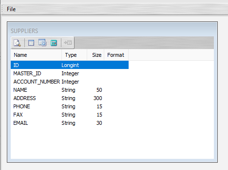
The extra fields in the SUPPLIERS File Dataview (above the first entered field ACCOUNT_NUMBER), are ID and MASTER_ID. These are automatically generated to enhance and support the building of the file relationships, and are not included in the mapping process.
Close the definition canvas once you are satisfied that you are extracting the correct records in the query by selecting Close from the File menu. You will return to the New File Definition window. Click Save to save and close the module.
The File Definition named Suppliers List (csv) will now appear in the structure tree under Configuration > Components > Data Definitions > File Definitions.
All required connections and definitions for this tutorial have now been configured. The mapping process is next.
What To Do With The Data - Creating Maps
The core component in the Statelake configuration is the Map. The Map brings together the connections and definitions in order to link all the parts together to facilitate the transportation of the data from the source to the destination file. The simplest one-to-one mapping just transfers the values, but more sophisticated mapping enables Statelake to perform a vast array of operations, including but not limited to data validation, data conversion, and the addition and removal of records through additional programming. This tutorial utilises a one-to-one map.
Designer will already be open. If not, open the Statelake module Designer for the selected configuration. An expanded structure tree is displayed on the left side of the screen.
Create The New Map
Follow the path Configuration > Components > Maps. Right‑click on Maps and choose New from the drop‑down list.
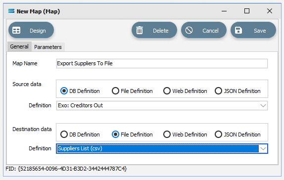
New Map appears as an entry under Maps. The New Map window contains two tabs - General and Parameters. The Parameters tab allows you to set other options, but for training purposes, we will be dealing with just the General tab. The following information is to be entered for the main map.
Map Name - this is the meaningful name that will identify the extraction process, and in this tutorial will be called Export Suppliers To File.
Source Data – activate the DB Definition radio button.
Definition – the DB Definition that was created for this configuration called Exo: Creditors Out can be selected from the pull-down list.
Destination Data – highlight the File Definition radio button.
Definition – the name of the File Definition that was created for this configuration called Suppliers List (csv) can be selected from the pull-down list.
Open The Map
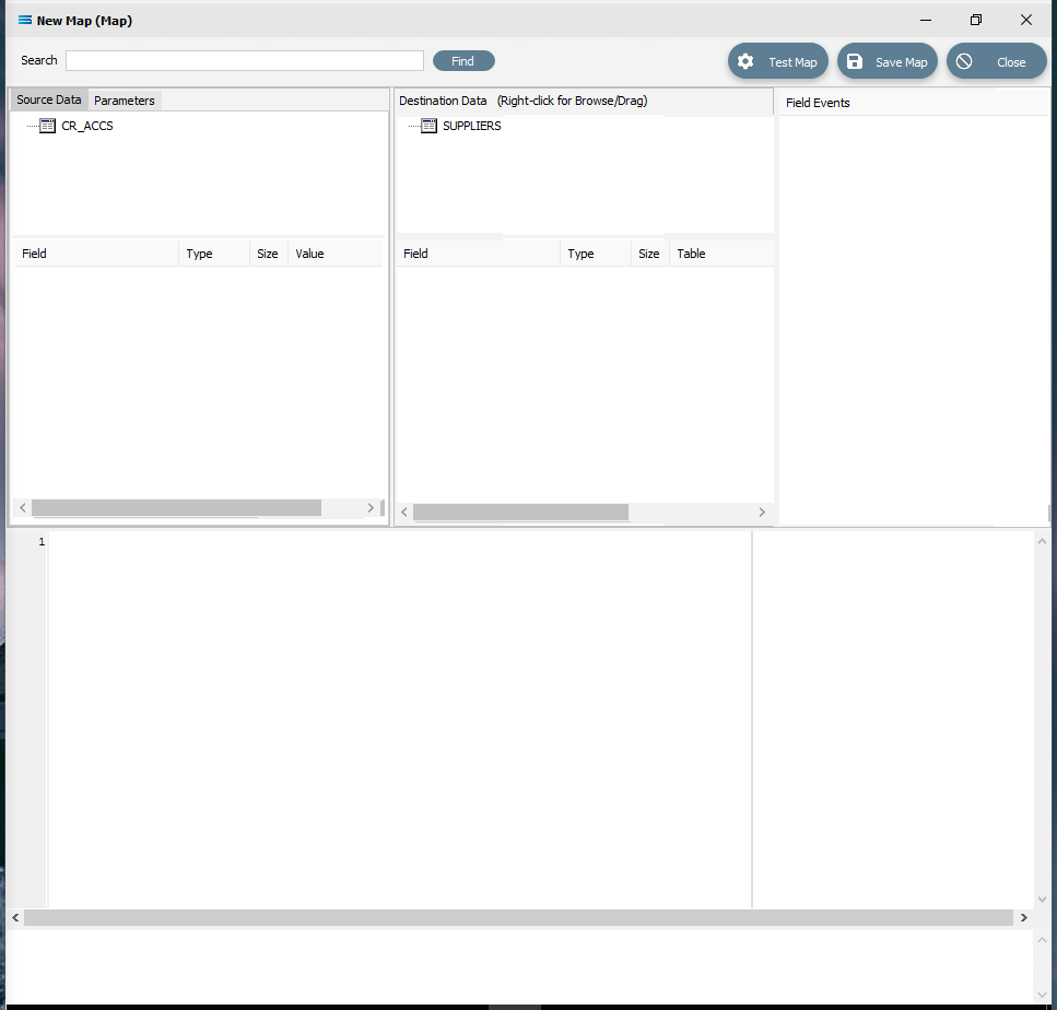
Click the Design button in the top left of the window to open the map designer window New Map.
The New Map screen is split into five distinct panes beneath the search bar.
Source is split into two with Source Data, and Parameters tabs. This is the definition of the source that data is to be read from.
Destination Data is also split into two. This is the definition that the data is to be written to.
Field Events on the top right side of the screen. This shows the events of the selected dataset or record.
Scripting Area beneath the Source Data and Destination Data panes. Where the script of each event is displayed and edited.
Compiler Messages below the Scripting Area and across the entire window. Messages that are returned by the compiler.
This first mapping operation is the linking of the datasets, so that for every record in the source dataset there is a corresponding record in the destination dataset.
In this tutorial we will link the source dataset table CR_ACCS to the destination SUPPLIERS dataset.
CR_ACCS is already showing in the Source pane, and SUPPLIERS is already showing in the Destination Data pane.
Populate The Map
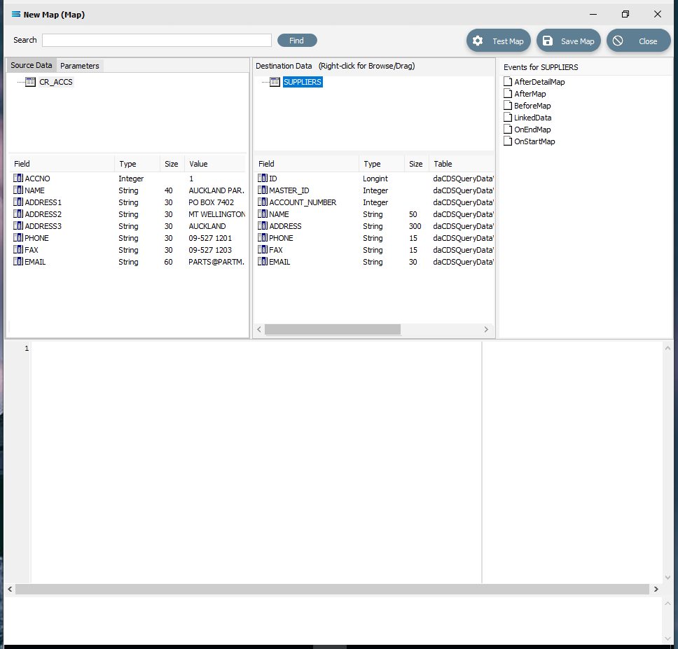
If you click on CR_ACCS in the Source Data pane you will see the field names that are in the table appear in the lower part of the pane.
If you click on SUPPLIERS in the Destination Data pane, the fields in this file will appear in the lower part of the pane. And the Field Events pane will populate with several Map events such as AfterMap and BeforeMap, and will be re-named to Events for SUPPLIERS.
Link The Datasets
Link the two datasets (source and destination) by dragging the CR_ACCS dataset and dropping it onto the SUPPLIERS dataset. You will see the established link appear in the Scripting Area, where the LinkedDataEvent code has been automatically generated showing that the two datasets are now connected.
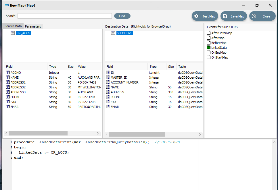 Close up of the script.
procedureLinkedDataEvent(varLinkedData:TdaQueryDataView);//SUPPLIERSbeginLinkedData := CR_ACCS;end;In the Field Events pane, the File icon beside the LinkedData event is now coloured GREEN.
A GREEN event icon signifies a successful code compilation for that event. A RED event icon indicates that an error has occurred and the code was not successfully compiled for that event. If the icon is in error, then correct the script and re-compile.
Link The Fields
Now link the fields using the same drag-and-drop technique - drag each field in turn from Source Data and drop it onto the associated Destination Data field, making sure that the destination field is highlighted before dropping the source field onto it else the link will not be successfully established.
ACCNO to ACCOUNT_NUMBER
NAME to NAME
PHONE to PHONE
FAX to FAX
EMAIL to EMAIL
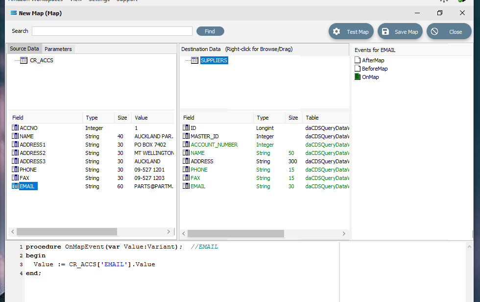
For each successful field drop, the colour of the field name in the Destination Data pane changes to GREEN, and an OnMapEvent procedure appears in the Scripting Area. In the Field Events pane, a set of events for each field has appeared, and each successful link is indicated by the OnMap event File icon being shown in GREEN.
You may see a message advising that the scripting had changed. If requested to Save, respond Yes.
The ADDRESS field in Destination Data is slightly different as we want to combine the three address fields from Source Data into this one Destination field, so it is not possible to do a simple drag-and-drop one-to-one mapping link. But the joining or concatenation of these three fields into one is easy.
Start with a simple one-to-one map by dragging ADDRESS1 from Source Data onto ADDRESS in Destination Data. ADDRESS will change to GREEN, the OnMap icon will show in GREEN in the Field Events pane, and this Statelake generated code will appear in the scripting area. The two forward slashes // denotes a comment on the script line.
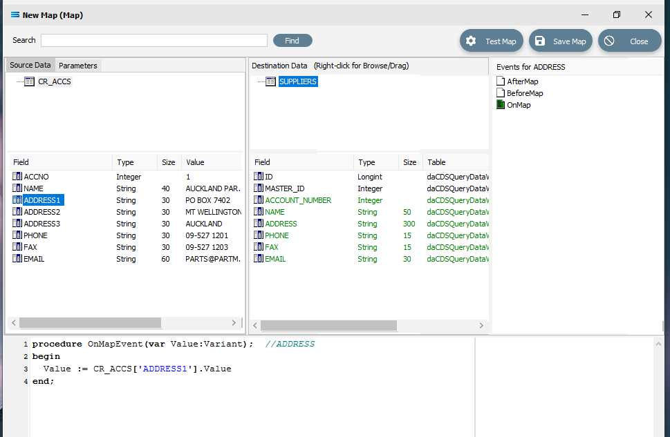 Close up of the scripting.
procedureOnMapEvent(varValue:variant);// ADDRESSbeginValue:= CR_ACCS['ADDRESS1'].Valueend;So with the first part of the address in place, we now want to add ADDRESS2. Drag the Source Data field ADDRESS2 and drop it into the Scripting Area at the very end of the script line Value := CR_ACCS['ADDRESS1'].Value. It is very important that it goes at the end of the line. The Scripting Area should now have the following code.
procedureOnMapEvent(varValue:variant);// ADDRESSbeginValue:= CR_ACCS['ADDRESS1'].Value CR_ACCS['ADDRESS2'].Valueend;To join these two fields together, it is necessary to add some code so that the line makes sense as a single line of code. The first thing is to replace the .Value after both ADDRESS1 and ADDRESS2 with the code .AsString to convert the data values into a string to ensure that Statelake can correctly handle any null values.
procedureOnMapEvent(varValue:variant);// ADDRESSbeginValue:= CR_ACCS['ADDRESS1'].AsString CR_ACCS['ADDRESS2'].AsStringend;The final step to concatenate or join these together, is to replace any spaces between the two field references by entering +‘ ‘+ (+’space’+) between AsString and CR_ACCS. These two fields are now joined into one.
procedureOnMapEvent(varValue:variant);// ADDRESSbeginValue:= CR_ACCS['ADDRESS1'].AsString+' '+CR_ACCS['ADDRESS2'].AsStringend;Repeat steps b, c, and d for ADDRESS3 in Source Data. And finally put a semi-colon ; at the very end of the line after the final AsString.;
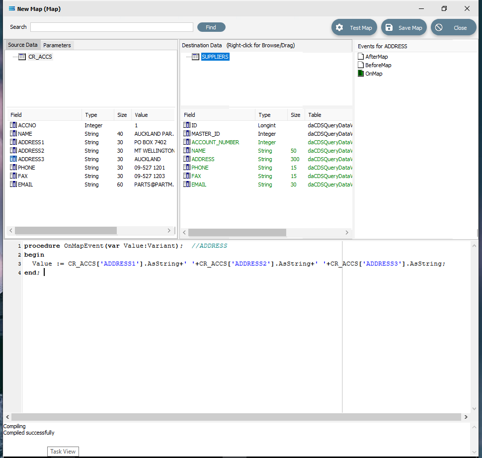 Close up of the final join.
procedureOnMapEvent(varValue:variant);// ADDRESSbeginValue:= CR_ACCS['ADDRESS1'].AsString+' '+CR_ACCS['ADDRESS2'].AsString+' '+CR_ACCS['ADDRESS3'].AsString;end;If you think you have made a mistake or typed something incorrectly into the Scripting Area, simply use the delete key or Ctrl-Z to undo, delete, or change it. You can treat it just like a text editor. To check your scripting syntax, you can right-click within the Scripting Area at any time, and select Test Compile. Any error will be displayed in the Compiler Messages section at the bottom of the window. If the script has been compiled with an error then the field in the Destination Data pane will display as RED, but will change to GREEN once corrected. A successful compile will also be indicated in this messages section.
If you want to start again or reverse the joining of the fields, you can easily remove the entire event and the script of the event by right-clicking on the OnMap icon in the Field events, and then selecting Clear for that event. Your actions will be completely backed out.
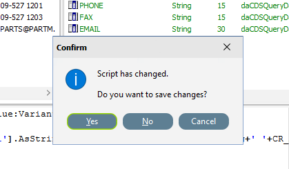
When you click out of the Scripting Area, you may see a message advising that the scripting had changed. If requested to Save, respond Yes.
In this tutorial we are linking the three addresses into one long string.
Linking or joining the three address lines in this way to create a single address string assumes two things – that each address will have a value in all three fields, and that a blank space (inserted as ‘ ‘) is sufficient to separate these three address lines within the address string in the destination flat file. But not all data is input the same, and there may be inconsistencies within the source file.
Depending on what the destination file is being used for, a single long string with no delimiting characters may not be acceptable, so it may be necessary to consider the purpose of the file prior to this step.
The code in the Scripting Area can be modified for instance to insert commas between the address lines (such as ‘, ‘) and a test can be performed for blank address lines to create a more useable destination flat file.
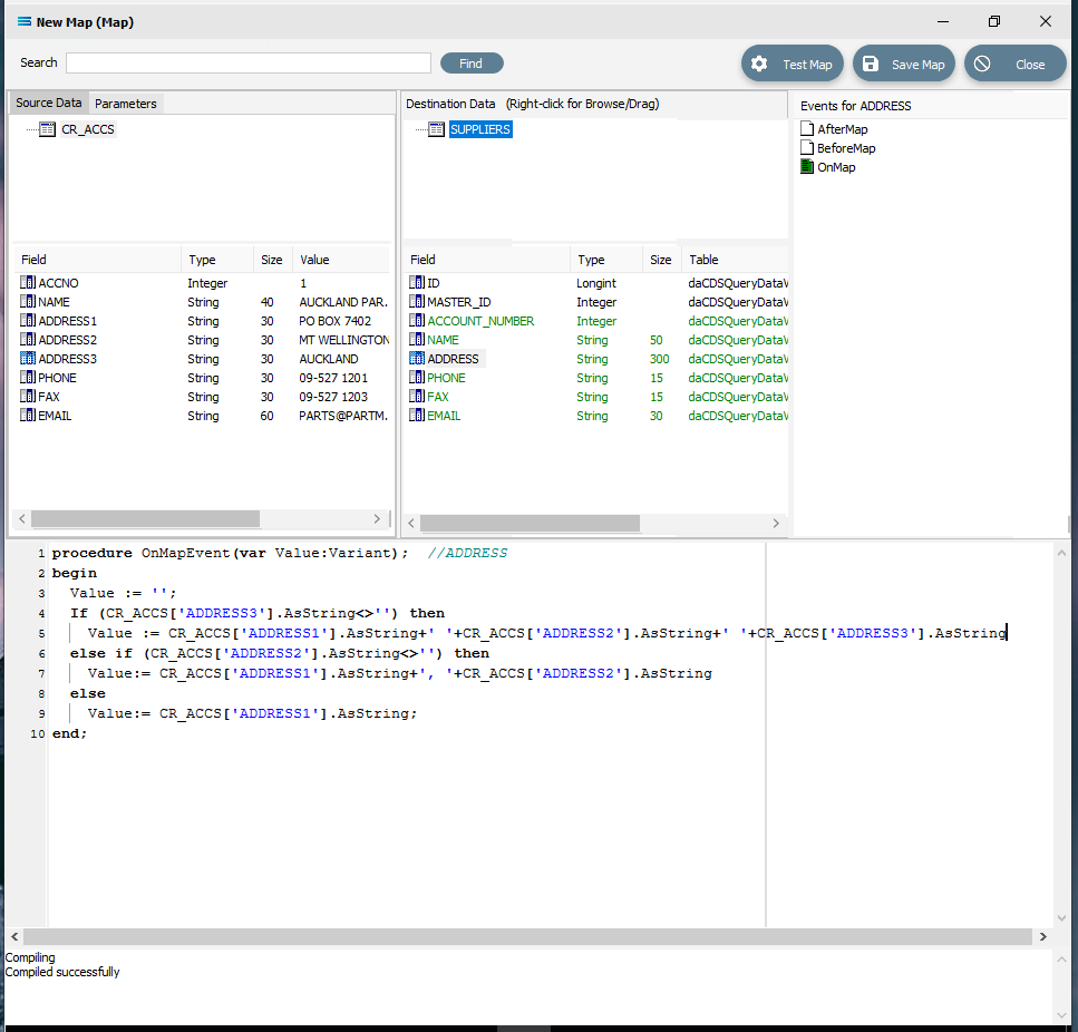
If you really want to get fancy and capture any discrepancies and have commas between the fields, you could replace the code with the following code.
procedure OnMapEvent(var Value:variant); // ADDRESSbegin Value:= ''; If (CR_ACCS['ADDRESS3'].AsString<>'') then Value:= CR_ACCS['ADDRESS1'].AsString+', '+CR_ACCS['ADDRESS2'].AsString+', '+CR_ACCS['ADDRESS3'].AsString else if (CR_ACCS['ADDRESS2'].AsString<>'') then Value:= CR_ACCS['ADDRESS1'].AsString+', '+CR_ACCS['ADDRESS2'].AsString else Value:= CR_ACCS['ADDRESS1'].AsString;end;To check your syntax and ensure that you have the code correct, you can right-click anywhere in the Scripting Area and select Test Compile. Any error will appear in the Message pane in the very bottom of the window. In this example, the code compile was successful.
If you move your cursor off the ADDRESS field in the Destination Data pane onto another field, you will be advised by a pop-up that the script has changed and prompted as to whether you want to save it. Reply in the affirmative and save the script.
Save the map and commit all of the mapping and scripting by clicking Save Map in the top right corner. Select OK to close the successful save message, then click on the Close button to close the Map. Click on Save at the designer New Map data entry window.
The Map named Export Suppliers To File will now appear in the structure tree under Configuration > Components > Maps.
Test The Map
Now test the map to ensure it is working.
Click on Export Suppliers to File under the Maps module again to open it, and click on the Design button.
The Export Suppliers To File map designer screen will display, with only the Source Data dataset CR_ACCS showing, and SUPPLIERS showing under Destination Data. SUPPLIERS will be displayed in GREEN.
Click Test Map in the top right corner of the screen, to execute the map in memory and generate a processing log which is then presented in a preview pane. A preview log with a light GREEN background indicates that the script ran without error. A PINK background indicates the presence of an error. This tutorial assumes the preview log is GREEN.
Close the pop-up preview of the log detail, and the destination definition query Suppliers List (csv) will be displayed on the canvas. Click on the Preview button to view the list of all of the processed records in a new window called Preview Data – SUPPLIERS. You will notice that the field ADDRESS now contains a concatenated string, and if you changed the script to the more complicated version, then the address will display with commas separating each previously separate field. The simpler code will generate a address with just a blank space between the 3 parts of the address. The more complicated script will highlight still several records however that are not correct – these appear to only have an ADDRESS1 and an ADDRESS3 in the source. If this was potentially going to be a serious issue, then you could return to the Map and change the script to take this combination into account. For the purposes of this tutorial, we will simply continue.
Using the X in the upper right corner, close the Preview Data pane.
Select File Close on the canvas, the Close button on the map designer screen, and the Save button on the Export Suppliers To File data entry window.
The Map has now been configured to produce a supplier list flat file out of the source database, and the links have been tested in memory to ensure that the map has all the information required for a successful extraction.
However, no actual physical destination file has been produced.
The next step pulls all the configured components together to produce the destination flat file.
What Action To Take - Creating Actions Manually
The final step is to pull all the definitions and configured components together to form an executable process to produce the destination flat file. This process is called an Action.
Designer will already be open. If not, open the Statelake module Designer for the selected configuration. An expanded structure tree is displayed on the left side of the screen.
Create The Action
Follow the path Configuration > Actions. Right‑click on Actions and choose New from the drop‑down list.
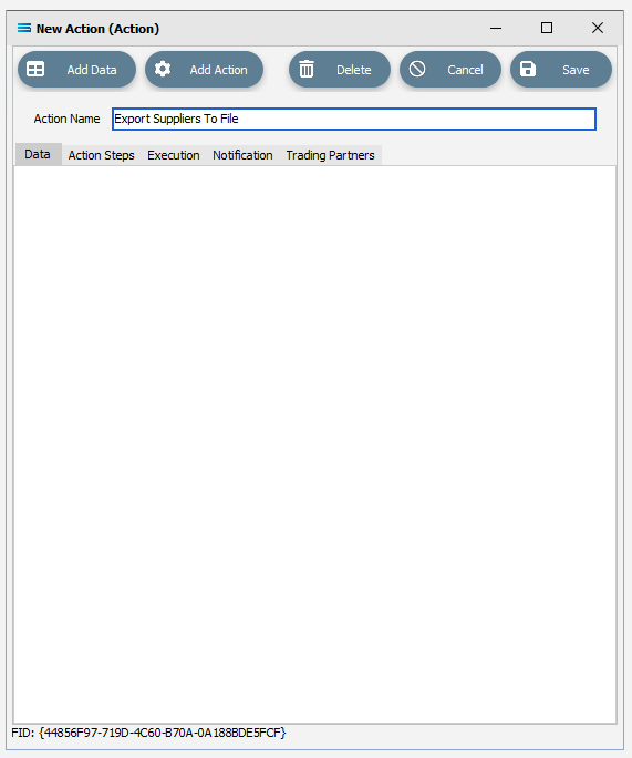
New Action appears as an entry under Actions. The New Action window will open. The window has five tabs – Data, Action Steps, Execution, Notification, and Trading Partners. In this tutorial only Data and Action Steps will be used. The following information is to be entered for the main map.
Action Name – this is a meaningful name for this Action. To keep the name consistent and to highlight the obvious relationship to the map Export Suppliers To File, we will give this action the same name, Export Suppliers To File.
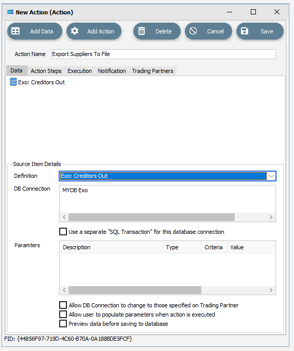
To configure the action, all of the necessary components need to be added. To do this click on the Add Data button on the top of the window, and select DB Definition. New DB Definition Item will appear under the Data tab.
Click on the New DB Definition Item in the Data pane. A new pane Source Item Details will open within the Data tab pane. This pane requires the following information:
Definition – select EXO: Creditors Out from the pull-down list.
DB Connection - this connection was input when the definition was configured, so the field is automatically populated with MYOB Exo.
Leave all other fields as set.
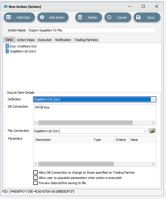
Click again on the Add Data button on the top of the window, and select File Definition. New File Definition Item will appear in the Data tab below the entry EXO: Creditors Out.
Every time you leave the Source Item Details pane, it will disappear into the background.
Click on the New File Definition Item in the Data pane. A new pane Source Item Details will open within the Data tab pane. This pane requires the following information:
Definition – select Suppliers List (csv) from the pull-down list.
DB Connection - this connection was input when the definition was configured, so the field is automatically populated with MYOB Exo.
File Connection – automatically populated. Leave as set.
Leave all other fields as set.
Click the Add Action button on the top of the window, and select Map Action. New Map Action Item will appear in the Action Steps tab.
Click on the New Map Action Item in the Action Steps pane. A new pane will open within the Action Steps tab pane. This pane requires the following information:
Map – select Export Suppliers To File from the pull-down list.
Source Data – select EXO: Creditors Out from the pull-down list.
Destination Data - select Suppliers List (csv) from the pull-down list.
Leave all other fields as set. Save To File will be ticked.
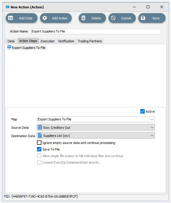
Click Save to save and close the New Action module.
The Action named Export Suppliers To File will now appear in the structure tree under Configuration > Actions.
Run The Action
To produce the suppliers flat file, you will need to run this action.
Open the Actions module again, right-click on Export Suppliers to File, and then select Run Action.
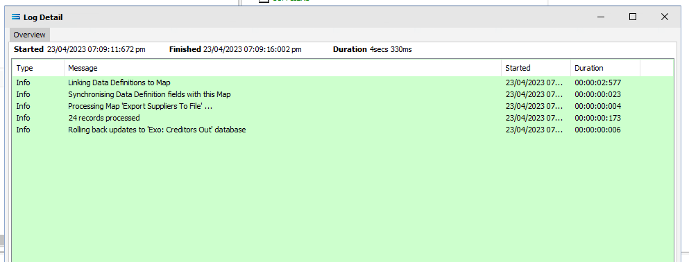
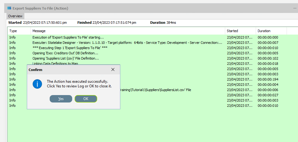
A window will pop-up showing the processing steps in a preview log, that will show the steps that were completed, how many records were extracted and processed, and where the destination file was saved. When the Action has been completed a status message will pop-up on screen indicating that processing is complete, and advising whether the process was successful or an error was encountered.
A successful Action will offer two choices – click Yes to review the log, or click OK to close the log without review.
To close the log after review, click the X in the upper right corner.
Logs can be re-opened as often as required. However, depending on the length of the preview log, you can also print screen or snip the Log for saving for later viewing.
Well Done!
The process is now complete, all modules have been closed, and the structure tree will be the only item on the Designer screen.
Summary
A suppliers list flat text file has now been created with data extracted from a Microsoft SQL Server database. In summary, the following things have been achieved for this configuration in this tutorial:
Two data connections have been created:
A DB Connection pointing to the database we will be reading from.
A File connection pointing to the path where the destination file will be saved.
Two data definitions have been created:
Identifying the structure of the table we will be reading from.
Creating the structure of the flat .CSV text file we will be writing to.
Statelake has received instructions on what to do with both data definitions by configuring a link process known as a Map.
And finally, an action has been created that has assembled all the components from steps 1,2, and 3, and has processed a series of instructions to extract the data from a database file and written these simple selected records into a list of supplier accounts in a flat text file.
These steps are crucial and represent the core steps of a Statelake configuration.
Quick Recap Quiz
Let’s put our understanding to the test!
How many tables within the source database are we extracting data from?
a. Two b. Three c. One
2. What type of destination file are we writing the extracted records to?
a. Flat file b. Excel c. XML
3. Which Statelake module is used to query the database?
a. DB Connection b. DB Definition c. Map
4. Which Statelake module facilitates the transformation of the data from the source to the destination?
a. Map b. File Connection c. Action
5. What technique is used to link fields together?
a. Copy-and-paste b. Click-and-swap c. Drag-and-drop
Next Steps
Congratulations on your progress so far. The next tutorials in this series are:
Tutorial 2 - Import Debtors Into A Custom Database
Tutorial 3 - Importing XML Purchase Orders Into A Database
Tutorial 4 - Extracting XML Invoices Out Of A Database
Tutorial 5 - Statelake Magic SQL
Tutorial 6 - Import CSV Purchase Orders Into A Database
Tutorial 7 - Exporting And Importing Configuration Data
Quick recap quiz answers
c 2. a 3. b 4. a 5. c