Tutorial 2: Import Debtors Into A Custom Database
This tutorial illustrates the simplest example of mapping into a database table. As we did in Tutorial 1, we will again use the Exo database Data_Demo as the data source via the DB Connection called MYOB Exo. And for this tutorial the destination will be a custom database table within the Statelake demo database.
Because there is no requirement for a File Definition or File Connection, these will not be defined in this tutorial.
In real-life terms, this tutorial examines how to integrate two systems – or how to export records out of an operational database, into a data warehouse or other reporting application.
Each step should be fully completed before processing to the next. As well as becoming more familiar with the Statelake components and modules, by completion of this tutorial you will be familiar with the process to:
Re-use existing components of a Statelake Configuration
Create a DB Definition for importing records into a single database table
It is most important before you proceed, to check and ensure that all of the training files have been copied as instructed. These files are an essential part of this tutorial.
Where The Data Is - Database Connections
In this tutorial, an Exo database will be used as the source. So, we can re-use the DB Connection named MYOB Exo that was established for the first tutorial - Exporting Creditor Accounts Into A Flat File Supplier List. However, a new connection will need to be created for the destination database table.
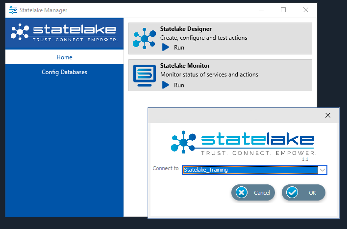
The first step is to make sure that Statelake module Designer for your selected configuration Statelake_Training is open. In Manager, select Home, then Run Statelake Designer, then select Statelake_Training from the drop-down menu and click OK.
Designer will open with an expanded structure tree is displayed on the left side of the screen.
Create DB Connection
Follow the path Configuration > Components > Data Connections > DB Connections. Click on DB Connections and MYOB Exo should be displayed. This connection to the database Data_Demo will be used for the source.
Clck on DB Connections - after completion of Tutorial 1, _Self and MYOB Exo should appear as available connections. Right-click on DB Connections and choose New from the drop-down list to create a new connection for the destination database Statelake_Demo.
New DB Connection should appear in the connection list. In the New DB Connection window the following information is to be entered.
Connection Name – some source databases will have obscure or convoluted names. This field is the user-friendly identifier name that will appear in the Statelake configuration, that references the source database. Enter My SL DB Demo. The two tick boxes Use Config Database and Use Config Database Server Only should be left blank.
The screen is then split into two tabs - General and Advanced. The Advanced tab allows you to set other options, but for training purposes, we will be dealing with just the General tab.
Connection Type – select the database engine that is to be used. In this instance, click the radio button Microsoft SQL Server.
Server Name – the server location for the destination database. As you used on the initial login screen to Microsoft SQL Server Management Studio, enter the server name which will either be <YOUR‑COMPUTER>\STATELAKE, or <YOUR‑COMPUTER>\SQLEXPRESS.
Database Name – the name of the database. Enter Statelake_Demo.
User Name and Password – fill these out with SQL authentication details or leave them blank to use Windows Authentication.
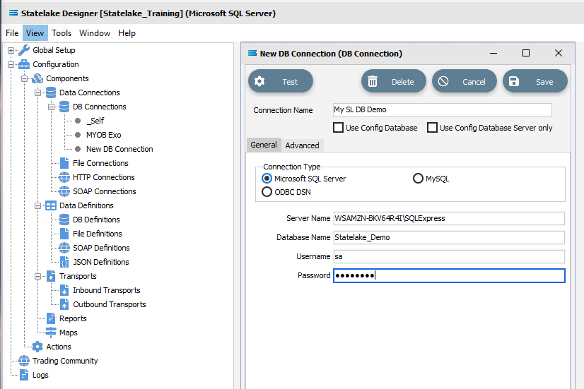
Click on the Test button in the top left of the window when all details are populated. If the details are all correct, you will be presented with a message “Connection Test Successful”. Otherwise, you will see the error reported by the database server. Click Ok to proceed.
It is impossible to cover all possible errors that nay come from a database connection because any error would be specific to the type of the database, and each database type may have hundreds of errors that can be generated. If you do not know what they error is, then try searching the web for documentation about errors for the type of database you are attempting to connect to.
If the connection test is successful, click Save and close the connection module.
The DB Connection named My SL DB Demo will now appear below MYOB Exo in the structure tree under Configuration > Components > Data Connections > DB Connections.
What The Data Is - Creating DB Definitions
The DB Definition tells Statelake what the data is, so that the proper fields can be accessed and the data extracted or written correctly. For this tutorial, this means defining the exact information to be extracted, and also identifying how any output file is to be constructed.
Sitting under the Data Definitions umbrella, Statelake uses the DB Definitions module to define these data structure components, and to design the database queries for both reading the data out of, and writing in to, any databases.
This tutorial illustrates creating definitions for reading the data from the Exo database called Data_Demo via the DB Connection called MYOB Exo, and another definition called Exo:Debtors Out for writing into the Statelake destination database Statelake_Demo.
Designer will already be open. If not, open the Statelake module Designer for the selected configuration Statelake_Training. An expanded structure tree is displayed on the left side of the screen. The first step is to create a DB Definition to read from a single database table as the source.
Create DB Definition (source)
Follow the path Configuration > Components > Data Definitions > DB Definitions. Right‑click on DB Definitions and choose New from the drop-down list.
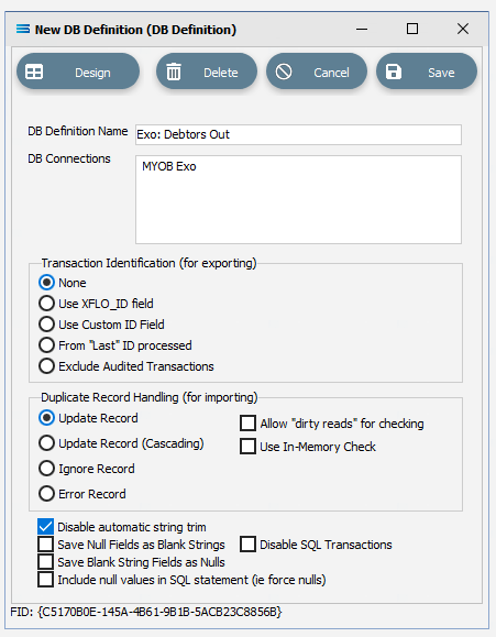
New DB Definition will appear in the structure tree. In the New DB Definition window the following information is to be entered.
DB Definition Name – the name that is meaningful and best describes the query/extraction. We will call this Exo: Debtors Out.
DB Connections – this is the name of the source database, identified by the meaningful name that was given in the DB Connections module. Right-click anywhere in the blank space in the box to see the Add pop-up, and a list of all the found connections will be displayed. Select the one you want from the list – in this tutorial, it will be MYOB Exo. You will notice that My SL DB Demo and _Self also appear on the list but these will not be selected at this stage.
Transaction Identification – leave with the defaults as set.
Duplicate Record Handling – leave with the defaults as set.
Disable Automatic String Trim – leave with the default as set. This is ticked.
Save Null Fields as Blank Strings – leave with the default as set.
Disable SQL Transactions – leave with the default as set.
Save Blank String Fields as Nulls – leave with the default as set.
Include Null Values in SQL statement – leave with the default as set.
Click Design in the top left of the window.
Create DB Dataview Query (source)
The blank definition designer canvas for New DB Definition will display. To start creating your query, click on the File menu in the top left corner, and choose New (or use the Ctrl+N).
The New Items window will open and only one item called DB Dataview will be displayed.
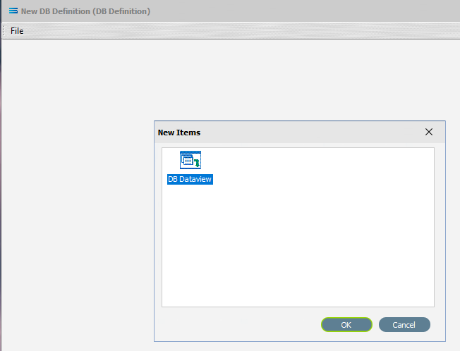
Click OK to add DB Dataview.
The Query Designer window will open.
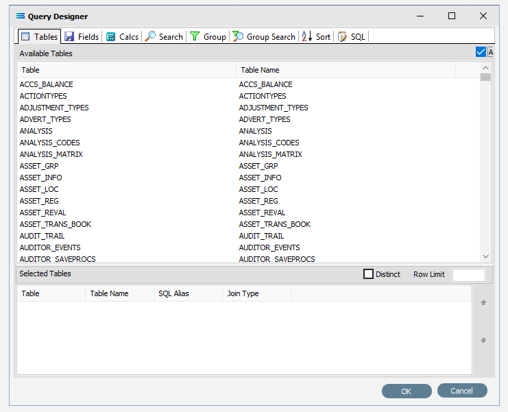
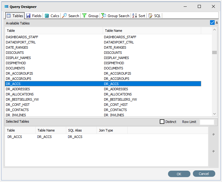
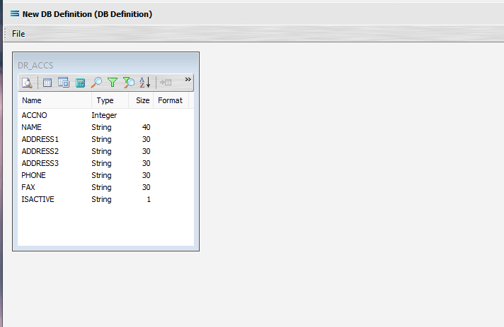
The first tab in the Query Designer is Tables. The upper pane contains a list of available tables in alphabetic order, and the lower pane will display the tables that you select. Scroll down the available tables to DR_ACCS (Debtor Accounts) and double-click to select it. It will appear in the lower pane as a selected table, while still remaining in the upper pane list.
You may have to expand the window height to see a greater number of entries.
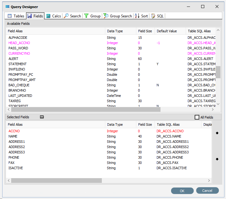
Move to the Fields tab, and add the following fields to query by double-clicking on them. The files will not automatically sort or appear in alphabetic sequence. Click on the field list header Field Alias to sort in descending order A-Z; click again to change to ascending order Z-A; then click again for a random sort.
ACCNO (account number)
NAME (account name)
ADDRESS1
ADDRESS2
ADDRESS3
PHONE
FAX
ISACTIVE
The fields are colour-coded in the Query Designer. RED indicates that the field is either calculated or is an automatically generated identity such as ACCNO. PINK indicates that the field does not allow null values such as with HEAD_ACCNO.
As you select fields from the Available Fields pane, they will appear in the Selected Fields pane, and disappear from the Available Fields pane.
Click on the SQL tab to see the SQL query that has been generated.
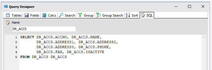
It lists the fields you selected and the table they are to be retrieved from. Note that the table name prefixes the field name and is separated by a full stop.
If you make a mistake and click on one of the fields in the Available Fields pane more than once in error, or click on a field that you do not want, simply double-click on the field you do not want in the Selected Fields pane to de-select it, and it will re-appear in the Available Fields pane.
Click OK at the bottom-right of the Query Designer to save the dataview and return to the definition canvas. The configured dataview will display, listing all of the selected fields. The DR_ACCS dataview window can be expanded as required.
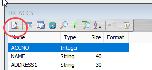
Preview Your Results
You can preview the data that will be returned by the query by clicking on the Preview button on the upper left corner (circled).
Click OK to close the preview pop-up window.
Close the definition canvas by selecting Close from the File menu. You will return to the Exo: Debtors Out window. Click Save to save and close the module.
The DB Definition named Exo: Debtors Out will now appear in the structure tree under Configuration > Components > Data Definitions > DB Definitions.
The next step is to create a DB Definition to write into a single database table as the destination. Designing this definition is almost identical to the definition you have just created to read from the source table.
Create DB Definition (destination)
Right‑click on DB Definitions again and choose New from the drop-down list.
Again, New DB Definition will appear in the tree structure under DB Definitions. In the New DB Definition window the following information is to be entered.
DB Definition Name – the meaningful name for this table will be My SL: Customers In.
DB Connections – this is the name of the destination database, identified by the meaningful name that was given in the DB Connections module. Right-click in the blank space in the box to see the Add pop-up, and a list of all the found connections will be displayed. This time select My SL DB Demo from the list.
Transaction Identification – leave with the defaults as set.
Duplicate Record Handling – leave with the defaults as set.
Disable Automatic String Trim – leave with the default as set. This box is ticked.
Save Null Fields as Blank Strings – leave with the default as set.
Disable SQL Transactions – leave with the default as set.
Save Blank String Fields as Nulls – leave with the default as set.
Include Null Values in SQL statement – leave with the default as set.
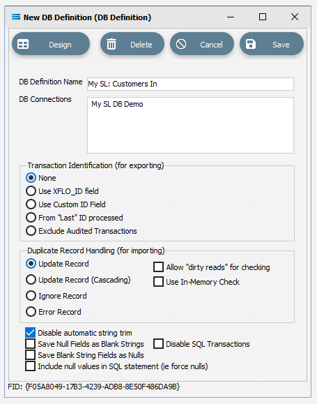
Click Design in the top left of the window.
Create DB Dataview Query (destination)
A blank definition New DB Definition designer canvas will display. To start creating your query, click on the File menu in the top left corner, and choose New (or use the Ctrl+N).
The New Items window will open and only one item called DB Dataview will be displayed. Click OK to add DB Dataview.
The Query Designer window will open.
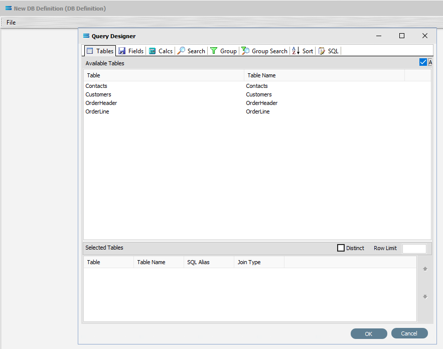
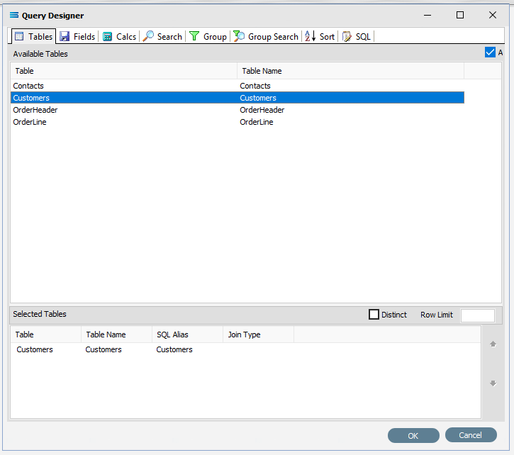
The first tab in the Query Designer is Tables. The upper pane contains a list of available tables in alphabetic order, and the lower pane will display tables selected from this list. You will see as a comparison, there are only a few tables listed in this dataset - Contacts, Customers, OrderHeader, and OrderLine. Select the Customers table by double-clicking to select it. It will appear in the lower pane as a selected table, but will remain visible in the upper pane.
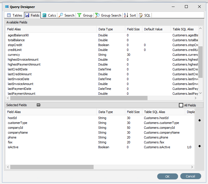
Move to the Fields tab, and just as you did in the source query, add the following fields to query by double‑clicking on them:
hostId
customerType
companyId
companyName
phone
fax
isActive
As you select fields from the Available Fields pane, they will move - appearing in the Selected Fields pane, and disappearing from the Available Fields pane.
Setting Field Parameters And Criteria
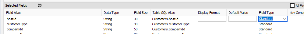
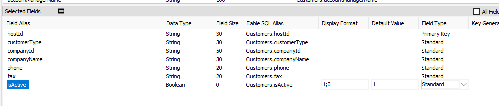
The selected field hostId is to be set to be the primary key.
On the lower section of the pane under Selected Fields, click hostId under the Field Alias heading to select and highlight the line. The Field Type for hostId should say Standard – in fact, all of the fields in this lower pane default to this value.
While the line is selected, select Primary Key from the pull-down list beside Standard under the Field Type heading.
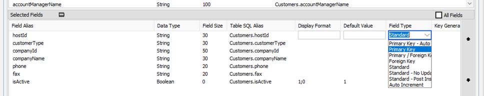
Setting the field hostId as the Primary Key for this destination dataset enables this field to determine whether incoming data from the source needs to be updated or inserted into the destination database. With this setting, if a record for the incoming hostId already exists in the table, then the rest of the fields in that record will be updated as appropriate, based on the incoming data. And if a record for the incoming hostId does not already exist, then a new record will be created. If a Primary Key is not used, then the DB Definition will always create new records i.e. be in insert mode only.
Specify the Display Format field for isActive to be 1;0 if it is not already displaying this value.
To ensure that boolean True and False values are handled correctly, this field needs to be forced to hold data that will be easily recognised and interpreted. So the value is converted into either a bit data type as 1 for True, and a 0 for False.
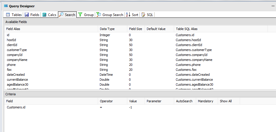
Click on the Search tab. A list of the table fields will display in the upper pane labelled as Available Fields. Double-click on id to add it to the Field column in the lower Criteria pane. It will display as Customers.id (table.field) and an equal sign = will automatically appear in the Operator column. Set the Value to -1 (minus one) on this line, to ensure that the DB Definition is empty when it is loaded into the Map. If this destination dataset holds any data, then Statelake will produce an error, so to successfully insert or update data into a populated table, the search criteria is set to a value that will not exist in the table (such as -1).
Click OK at the bottom-right of the Query Designer to save the dataview and return to the definition canvas. The configured dataview Customers will display, listing all of the selected fields which can be expanded as required.
Close the definition canvas by selecting Close from the File menu. You will return to the DB Definition window. Click Save to save and close the module.
The DB Definition named My SL: Customers In will now appear in the structure tree under Configuration > Components > Data Definitions > DB Definitions.
What To Do With The Data - Creating Maps
There have now been two DB definitions created for this tutorial., so the next step is to create a Map to pull the data from one, into the other.
Designer will already be open. If not, open the Statelake module Designer for the selected configuration. An expanded structure tree is displayed on the left side of the screen.
Create The Map
Follow the path Configuration > Components > Maps. Right‑click on Maps and choose New from the drop‑down list.
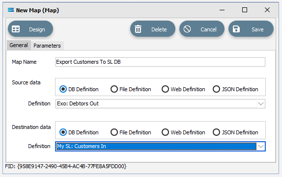
New Map will appear in the tree structure. The New Map window contains two tabs - General and Parameters. The Parameters tab allows you to set other options, but for training purposes, we will be dealing with just the General tab. The following information is to be entered for the main map.
Map Name - this is the meaningful name that will identify the extraction process. Enter Export Customers To SL DB.
Source Data – highlight the DB Definition radio button.
Definition – the DB Definition that was created for this configuration called Exo: Debtors Out can be selected from the pull-down list.
Destination Data – highlight the DB Definition radio button.
Definition – the name of the DB Definition that was created for this configuration called My SL: Customers In can be selected from the pull-down list.
Open The Map
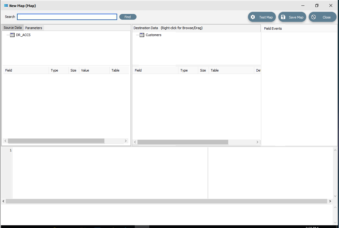
Click the Design button in the top left of the window to open the map designer window New Map.
The New Map screen is split into five distinct panes beneath the search bar.
Source is split into two panes with Source Data and Parameters tabs. This is the definition of the source that data is to be read from.
Destination Data is also split into two panes. This is the definition that the data is to be written to.
Field Events on the right side of the screen. The events of the selected dataset or record.
Scripting Area beneath the Source Data and Destination Data panes. Where the script of each event is displayed and edited.
Compiler Messages below the Scripting Area. Messages that are returned by the compiler.
In this tutorial we will link the source dataset table DR_ACCS to the destination Customers dataset. DR_ACCS is already showing in the Source pane, and Customers is already showing in the Destination Data pane.
Link The Datasets And Populate The Map
Link the two datasets by dragging the DR_ACCS source dataset and dropping it onto the Customers destination dataset. Once a successful link has been established you will see the established link appear in the Scripting Area, where the LinkedDataEvent code has been automatically generated.
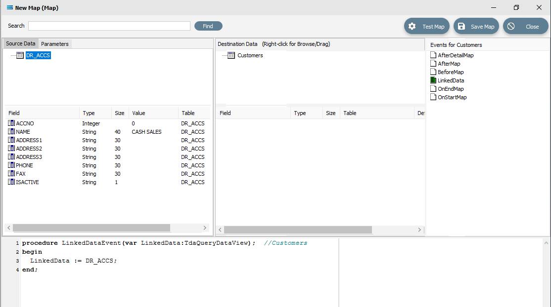
Close up of the code as below.
procedureLinkedDataEvent(varLinkedData:TdaQueryDataView);// CustomersbeginLinkedData := DR_ACCS;end;A list of events has also appeared in the Field Events pane, and this has been renamed to Events For Customers. The file icon beside the LinkedData event is now coloured GREEN which indicates a successful compilation for this event. If the icon was RED, this would indicate that the code was not successfully compiled.
Link The Fields
Click on the DR_ACCS table to list the fields in the Field pane under Source Data, and click on the Customers table to display the fields in the Customers table under Destination Data. Now link the fields using the same drag and drop technique used previously: drag the fields from the Source DR_ACCS field and drop it onto the fields for the Destination Data table CUSTOMERS, making sure that the destination field is highlighted before dropping the source field onto it else the link will not be successfully established:
ACCNO to hostId
NAME to companyName
PHONE to phone
FAX to fax
ISACTIVE to isActive
For each successful field drop, the colour of the field name in the Destination Data pane changes to GREEN, and an OnMapEvent procedure appears in the Scripting Area. In the Field Events pane, a set of events for each field has appeared, and each successful link is indicated by the OnMap event file icon being shown in GREEN.
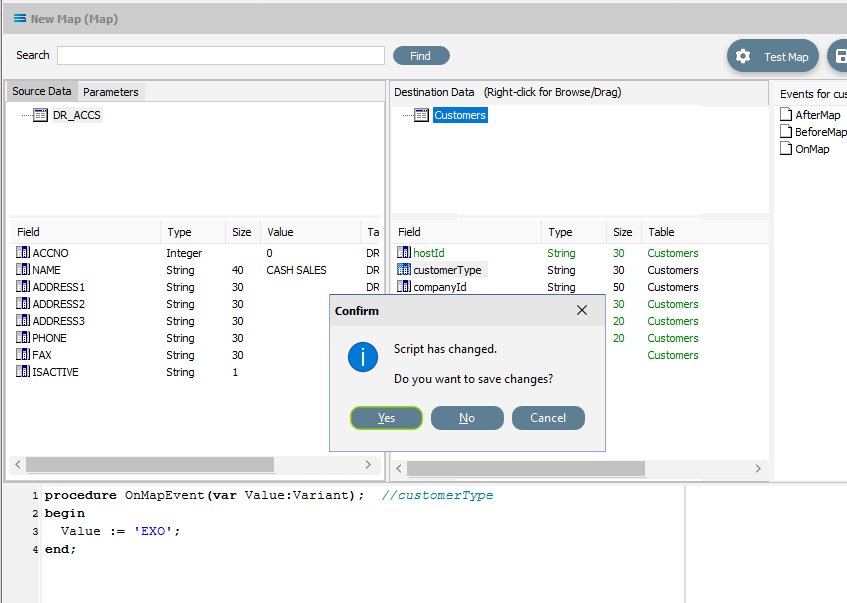
Click on the customerType field in the destination area, and then in the Scripting Area to manually specifiy the mapping for the field. The following code will be manually generated:
procedureOnMapEvent(varValue:variant);// customerTypebeginValue :=end;Append to the third line and type ‘EXO’; (quote EXO quote semi-colon) immediately after the Value :=. Now click on customerType in the destination pane, and when you click out of the Scripting Area, if you are prompted to save your changes, click Yes.
The Compiler Messages area should tell you that the compile was successful. If not, check your spelling and try again.
In this tutorial the field companyId is going to be exactly the same as the field hostId in the destination dataset. Therefore, you are able to map the value of companyId from the already mapped hostId, rather than mapping DR_ACCS:ACCNO again. There are a couple of steps to perform to achieve this.
Click on the companyId field, and then click into the blank Scripting Area. A blank OnMapEvent script will be generated.
Right-click on the hostId field in the destination area. You will see that the cursor shape has changed into a greyed box and that you are in effect actually dragging the field.
Left-click in the Scripting Area at the end of the 3rd line after Value :=. to append the value D_Customers[‘hostId’].Value to the line.
The script has now become:
procedureOnMapEvent(varValue:variant);// companyIdbeginValue := D_Customers['hostId'].Value;end;Type a semi-colon at the end of the line after .Value to complete it. Click on companyId in the destination pane and when you click out of the Scripting Area, if you are prompted to save your changes, click Yes. The companyId field will change to GREEN.

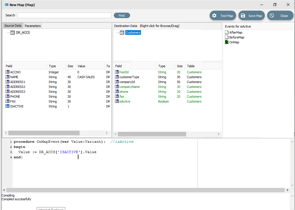
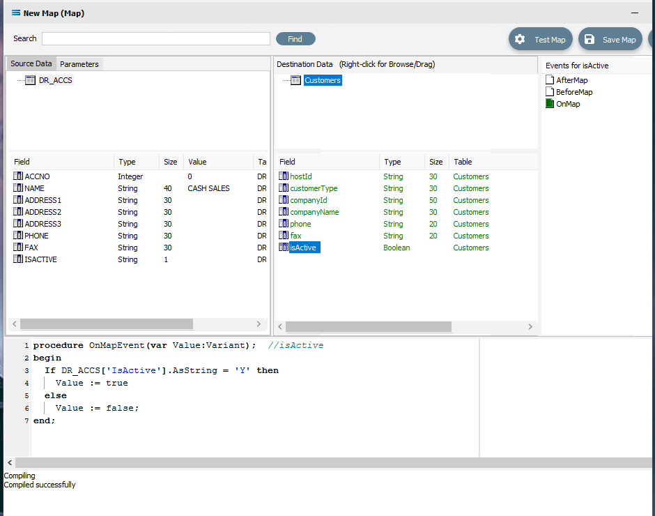
In the source, the ISACTIVE field is currently of the type String, while the isActive field in the destination is of the type Boolean. To assign the value in one field to another field, the types must be the same - you cannot cross-type. So we cannot just simply assign DR_ACCS:ISACTIVE to Cutomers:IsActive. The ISACTIVE field values in the source dataset will need to be translated into Boolean to match the destination field type.
ISACTIVE with a string type can have either Y or N values. Click on isActive from the destination dataset to load the script into the Scripting Area.
Type in a decision tree to change the script code to the following, as illustrated below. Note that the if line, the else line, and the line Value := true do not have a semi-colon on the end because neither line is the end of the IF statement (ELSE is following it).
procedureOnMapEvent(varValue:variant);// isActivebeginIfDR_ACCS['ISACTIVE'].AsString ='Y'thenValue :=trueelseValue :=false;end;Click isActive in the destination area to save the script. Respond Yes to the saving the change of script.
Save the Map and commit all of the mapping and scripting by clicking Save Map in the top right corner. Select OK to close the successful save message. then click on the Close button to close the map designer window.
To commit all the mapping and scripting, click on the Save button to save and close the mapping module.
The Map named Export Customers To SL DB will now appear in the structure tree under Configuration > Components > Maps.
Test The Map
Now test the Map to ensure it is working:
Open the Maps module again by clicking on Export Customers To SL DB, and click on the Design button.
The Export Customers To SL DB map designer screen will display, with only the Source data DR_ACCS showing, and Customers showing under Destination Data.
Click Test Map in the top right corner of the screen, to execute the map in memory and generate a processing log which is then presented in a preview pane. A successful test will display the log with a light green background, but if an error is encountered, then the log background will be pink.
Close the pop-up preview of the log and the destination definition query Export Customers To SL DB will be displayed on the canvas. Click on the Preview button to view the list of all of the processed records.
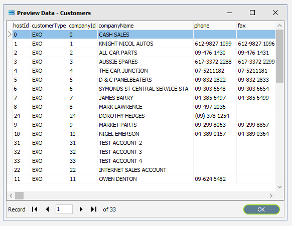
Using the X in the upper right corner, close the Preview Data pane, or click OK.
Select File Close on the canvas, then the Close button on the map designer screen, followed by the Cancel button on the Export Customers To SL DB data entry window.
The Map has now been configured to insert records into another dataset, and the links have been tested in memory to ensure that the map has all the information required for a successful extraction. However, no actual database activity has been generated.
The next step pulls all the configured components together to produce the destination dataset
What Action To Take - Creating An Action
The final step is to pull all the definitions and configured components together to form an executable process to follow the Map and produce the destination database. This process is called an Action. While the details for an Action can be created manually, Statelake can also generate the Action for you.
Designer will already be open. If not, open the Statelake module Designer for the selected configuration. An expanded structure tree is displayed on the left side of the screen.
Create The Action Automatically
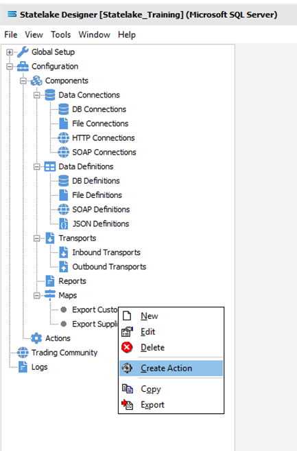
Follow the path Configuration > Components > Maps. Click on Maps to expand the tree. Right‑click on the map you have just created called Export Customers To SL DB, and choose Create Action from the drop‑down list.
All the relevant fields will be populated and components will be automatically added to this Action.
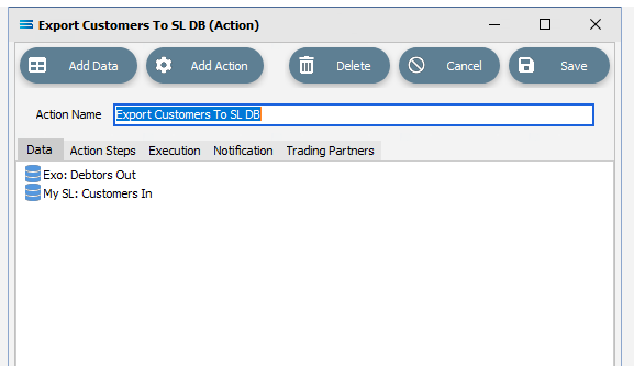
There is no need to do anything with this window, except select Save on the top right corner to close the module.
The Action named Export Customers To SL DB will now appear in the structure tree under Configuration > Actions.
Run The Action
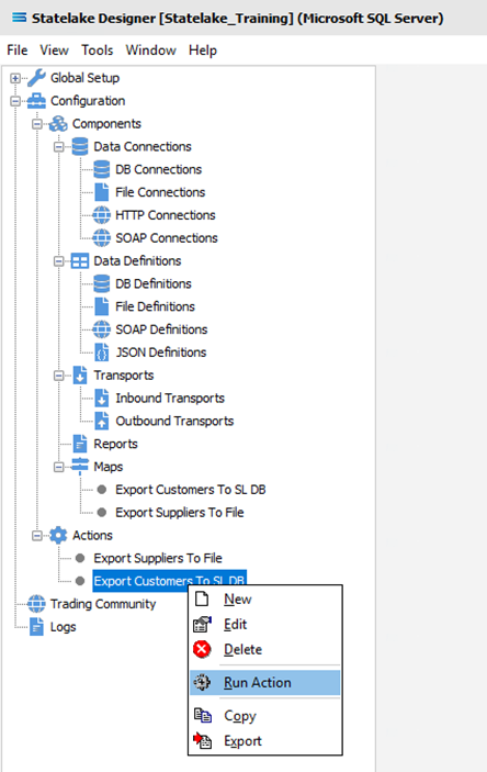
To run this Action, click on Actions, then right-click on the Export Customers To SL DB Action, then select Run Action from the available options.
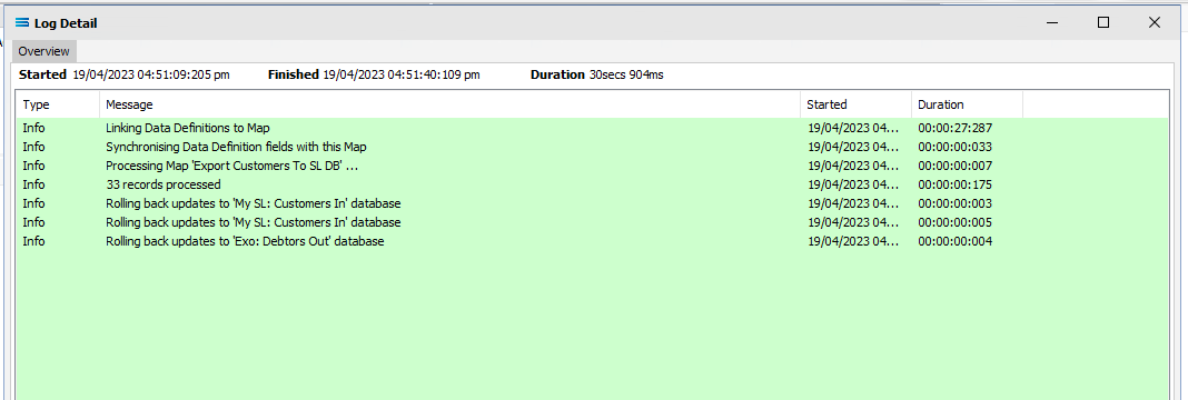
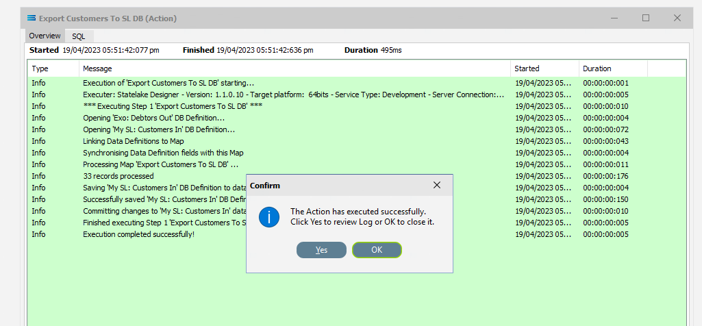
A window will pop-up showing the processing steps in a preview log, which will itemise and show the steps that were completed, how many records were extracted and processed, and where the destination file was saved. When the action has been completed a status message will pop-up on screen indicating that processing is complete, and advising whether the process was successful or an error was encountered. A successful Action will offer two choices – click Yes to review the log, or click OK to close the log without review.
To close the log after review, click the X in the upper right corner.
Logs can be re-opened at any stage as many times as required. To review a Log from the Manage Logs window, double-click on the Log entry as required. To drill into any line on the Log, double-click on the line to see more detail.
The process is now complete, all modules have been closed, and the structure tree will be the only item on the Designer screen.
Reviewing The Log
The Logs from the running of all Actions can be accessed and reviewed at any time.
Click on Logs and the Manage Logs window will open, and a list of all logs written will appear.
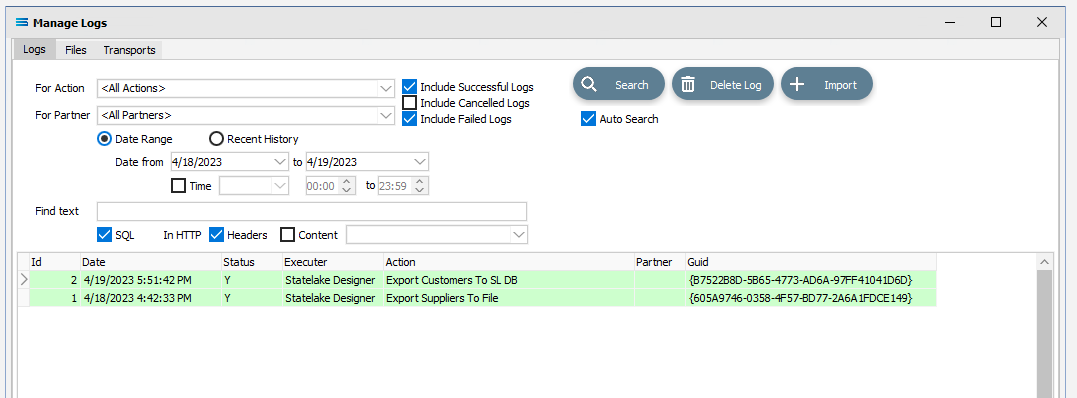
Double-click on the log Export Customers to SL DB under the Action column to open the log.
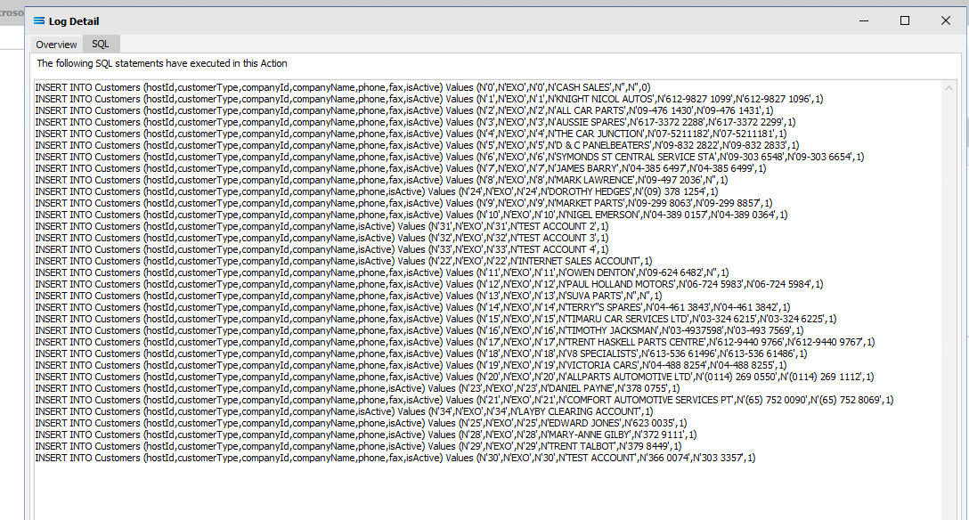
Click on the SQL tab to see the SQL executed against the destination database. You can see how the records were inserted into the destination database.
Close the log by clicking the X. Then close the Manage Logs window by clicking the X in the top right corner.
If you run the Action again and then re-check the log – you will see another entry has been written to the list.
Summary
You have now successfully read data from one dataset and written that data into another. In summary these are things that have been achieved for this configuration in this tutorial:
Database definitions have been configured to enable writing into a dataset.
Several simple mapping scripts have been introduced.
The use of a decision tree in the mapping script.
Data type conversion during scripting.
Querying databases from the map during processing.
Quick Recap Quiz
This was a complex tutorial, so you have done well! Here is an easy recap to test your knowledge.
What module would define the tables and columns that you want to read from, or write to, a database?
a. Map b. DB Connection c. DB Definition
2. What is a decision tree?
a. Available options b. Possible outcomes c. Isaac Newton’s apple tree
3. What is a primary key?
a. Main data identifier b. How to unlock a record c. A password
4. In what Statelake module would scripting primarily be employed?
a. Action b. Map c. File Definition
5. What is the purpose of an Action?
a. To start processing b. To create a file structure c. To define a database
6. Where would you find a LinkedDataEvent?
a. File Definition b. Action c. Map
7. In the absence of a primary key, what is the default behaviour of a DB Definition when the database is used as a destination?
a. Update b. Create c. Delete
8. What module would you use to define a database name and access credentials?
a. DB Definition b. Action c. DB Connection
Next Steps
You have done really well and made excellent progress!
The next tutorials in this series are:
Tutorial 3 - Importing XML Purchase Orders Into A Database
Tutorial 4 - Extracting XML Invoices Out Of A Database
Tutorial 5 - Statelake Magic SQL
Tutorial 6 - Import CSV Purchase Orders Into A Database
Tutorial 7 - Exporting And Importing Configuration Data
Quick recap quiz answers
c 2. b 3. a 4. b 5. a 6. c 7. b 8. c
How well did you fare?