Tutorial 4: Extracting XML Invoices Out Of A Database
This tutorial is the largest and most complex in this series so far. It calls on all of the skills and knowledge that you have gained as you have worked through the tutorials up to this point, and illustrates many of the advanced features and functionality of the Statelake software. It is recommended that are familiar and comfortable with the contents of the previous tutorials before proceeding.
This tutorial illustrates a real-life situation, where a business sends out electronic invoices to its customers, records are extracted from a source database into a destination .XML file, and two-tier structures will be mapped – invoice headers and invoice lines. This tutorial will also introduce the Trading Community functionality and ways of marking extracted records.
The configuration for this tutorial will be covered in phases. Firstly, the basic functionality will be implemented to the point of a working Action. Secondly, additional functionality will be discussed and added.
Each step should be fully completed before progressing on to the next. By the end of this tutorial you will have the necessary skills and knowledge to:
Map a two-tier database structure into a two-tier file structure
Join several tables together in the same DB Dataview
Expose the DB Definition search criteria to the user
Write out a single file per transaction
Create and use Trading Community
Create and use Outbound Transports
Mark transactions as extracted, using settings within the DB Definition
It is most important before you proceed, to check and ensure that all of the training files have been copied as instructed. These files are an essential part of this tutorial.
XML Files
XML files differ from flat data files because they contain information scattered within the file that relates to the file structure, interspersed with the actual data values. This format tends to make XML files larger in size, but can also make them easier to read.
For example, an order number in an XML file might appear as:
<OrderNumber>12345</OrderNumber>XML also has the advantage of using schema files. These are separate from the data files, and describe the structure of the incoming XML data file, along with any validation rules that each data file must comply with.
The format of these schema files determine how the incoming data is translated and typically have a file name ending with .xsd, whereas XML data files have an .xml file extension.
The following examples show a simple XSD schema file, and the corresponding XML data file.
Simple XML Schema Definition (.XSD) For An Order
<?xml version="1.0"?><xs:schema attributeFormDefault="unqualified" elementFormDefault="qualified" version="1.0" xmlns:xs="http://www.w3.org/2001/XMLSchema"><xs:element name="OrderHeader" type="OrderHeaderType"/><xs:complexType name="OrderHeaderType"> <xs:sequence> <xs:element name="OrderNumber" type="xs:string" minOccurs="1" maxOccurs="1" /> <xs:element name="OrderDate" type="xs:date" minOccurs="1" maxOccurs="1" /> <xs:element name="OrderLine" type="OrderLineType" minOccurs="1" maxOccurs="unbounded" /> </xs:sequence></xs:complexType><xs:complexType name="OrderLineType"> <xs:sequence> <xs:element name="LineNumber" type="xs:int" minOccurs="1" maxOccurs="1" /> <xs:element name="ProductCode" type="xs:string" minOccurs="1" maxOccurs="1" /> <xs:element name="OrderQuantity" type="xs:int" minOccurs="1" maxOccurs="1" /> </xs:sequence></xs:complexType></xs:schema>Simple XML Data File (.XML) For The Same Order
<OrderHeader> <OrderNumber>12345</OrderNumber> <OrderDate>26-10-2011</OrderDate> <OrderLine> <LineNumber>1</LineNumber> <ProductCode>ABC</ProductCode> <OrderQuantity>10</OrderQuantity> </OrderLine> <OrderLine> <LineNumber>2</LineNumber> <ProductCode>XYZ</ProductCode> <OrderQuantity>3</OrderQuantity> </OrderLine></OrderHeader>Where The Data Is - Database Connections
To extract invoice data out of a database into an XML file, it is necessary to configure the required connections for the database and file, the definitions for the database and file, a Map and an Action. The Exo database will again be used as our source, so the DB Connection into MYOB Exo that has already been established in earlier tutorials can be used.
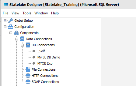
The first step is to make sure that the Statelake module Designer for your selected configuration Statelake_Training is open. An expanded structure tree is displayed on the left side of the screen.
Follow the path Configuration > Components > Data Connections > DB Connections. Click on DB Connections and MYOB Exo should be displayed.
Where The Data Is - File Connections
As we know, the File Connections module also sits under the Data Connections umbrella, and is the configuration module that points to a specified file directory that will hold the output or destination file. In this tutorial, the output file will be an Exo database. As we did for Tutorial Three, a new file connection for the input file needs to be created.
Designer will already be open. If not, open the Statelake module Designer for your selected configuration, Statelake_Training. An expanded structure tree is displayed on the left side of the screen.
Create File Connection
Follow the path Configuration > Components > Data Connections > File Connections. Right‑click on File Connections and choose New from the drop-down list.
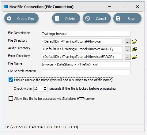
An item called New File Connection will appear in the structure tree. In the New File Connection window the following information is to be entered.
File Description – the name that is meaningful and best describes the output file. In this tutorial it will be Training: Invoice.
File Directory – the directory location for the destination output file. Enter <DefaultDir>\Training\Tutorial4\Invoice and use the tab key to proceed out of the field.
The <DefaultDir> tag refers to the default file path already set-up within the Statelake General Setup, under Global Setup. By default, C:\ProgramData\FlowSoftware\Statelake\Files will be the file directory path referenced by this tag.
c. Audit Directory – will be automatically populated when you tab out of File Directory.
d. Error Directory – will be automatically populated when you tab out of File Directory.
Statelake used two sub-directories to manage files - AUDIT and ERROR. When a file is successfully processed in, or successfully sent after being written out, it is moved into the AUDIT directory. If an error occurs during file processing, the file is moved into the ERROR directory.
e. File Name – is the actual name of the output file. We will use special tags inside the file name. <DateStamp> is a special tag that will be replaced by the current date and time when the file is created. <FileNo> is a special tag that will be replaced by the number of the file being written in the execution of that particular Action. Type in Invoice_<DateStamp>_<FileNo>.xml.
f. File Search Pattern - used by Statelake when files are being read. Leave this field blank.
g. Ensure Unique File Name – tick this box to add a number to the file name to ensure that the file name will be unique and will not overwrite a file already in the output folder. In this instance, leave this unticked.
h. Allow This File To Be Accessed – for this tutorial leave unticked.
If the sub-directories you have specified do not yet exist or you are not sure whether they exist, you will need to check by clicking on the button Create Dirs which is located on the top left of the window. If the directories do not exist, they will be created, else they will be confirmed as current and available by display of the pop-up message “File connection directories checked/created successfully”.
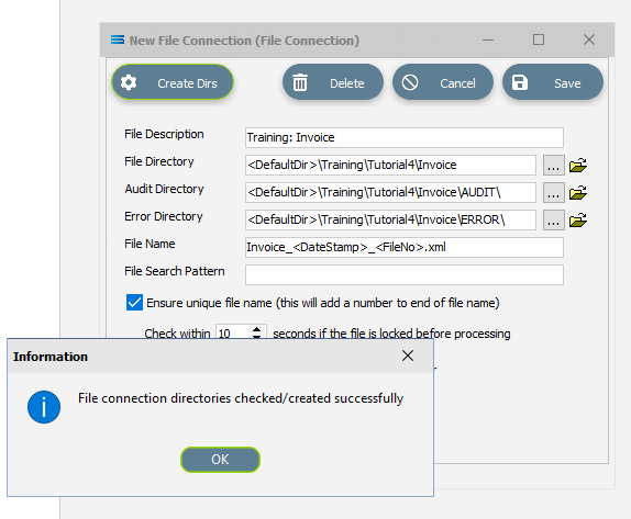
Click OK in response to the successful creation message.
Click Save when all details are entered to save and close the module.
The File Connection named Training: Invoice will now appear in the structure tree under Configuration > Components > Data Connections > FIle Connections.
What The Data Is - Creating DB Definitions
You should now be familiar with DB Definition sitting under the Data Definitions umbrella,
DB Definition tells Statelake what the data is, so that the proper fields can be accessed and the data extracted correctly, which means defining the exact information to be extracted, and also identifying how the output file is to be constructed.
For this tutorial, a database or DB Definition is created for extracting the invoice data.
Designer will already be open. If not, open the Statelake module Designer for the selected configuration Statelake_Training. An expanded structure tree is displayed on the left side of the screen.
Create DB Definition
Follow the path Configuration > Components > Data Definitions > DB Definitions. Right‑click on DB Definitions and choose New from the drop-down list.
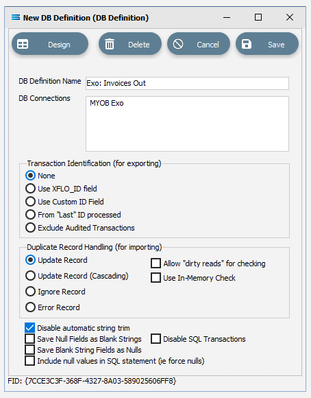
An item called New DB Definition will appear in the structure tree. In the New DB Definition window the following information is to be entered.
DB Definition Name – the meaningful name in this instance will be Exo: Invoices Out.
DB Connections – this is the name of the source database, identified in the DB Connections module. Right-click anywhere in the box to see the Add pop-up, follow the arrow and select MYOB Exo.
Transaction Identification – leave with the defaults as set.
Duplicate Record Handling – leave with the defaults as set.
Disable Automatic String Trim – leave with the default as set. This field will be ticked.
Save Null Fields as Blank Strings – leave with the default as set.
Disable SQL Transactions – leave with the default as set.
Save Blank String Fields as Nulls – leave with the default as set.
Include Null Values in SQL statement – leave with the default as set.
Click Design in the top left of the window.
Create DB Dataview Query
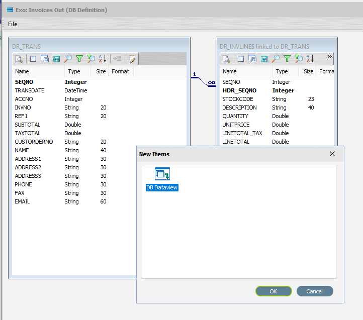
A blank definition designer canvas will display. To start creating your query, click on the File menu in the top left corner, and choose New (or use the Ctrl+N).
The New Items window will open and only one item called DB Dataview will be displayed.
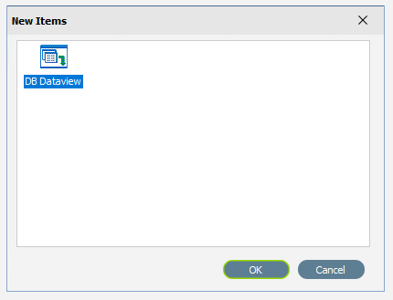
Click OK to add DB Dataview.
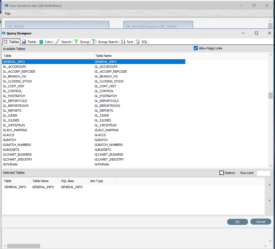
The Query Designer window will open.
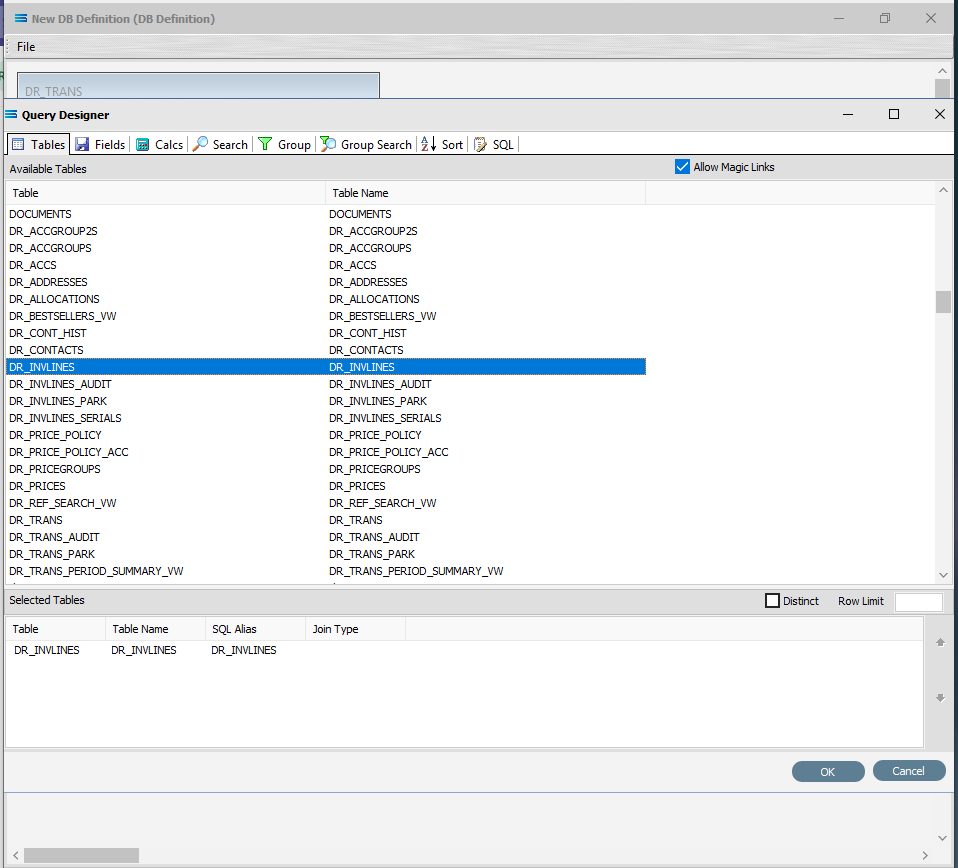
The first tab in the Query Designer is Tables.
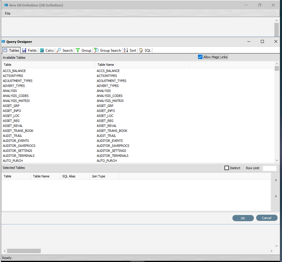
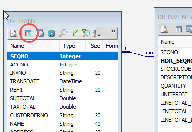
Scroll down the available tables to DR_TRANS (Debtor Transactions) and double-click to select it. It will appear in the lower pane as a selected table, but will also remain visible in the Available Tables list.
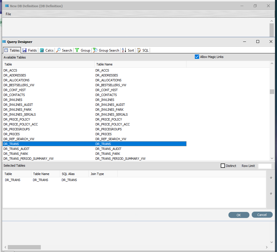
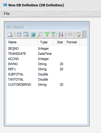
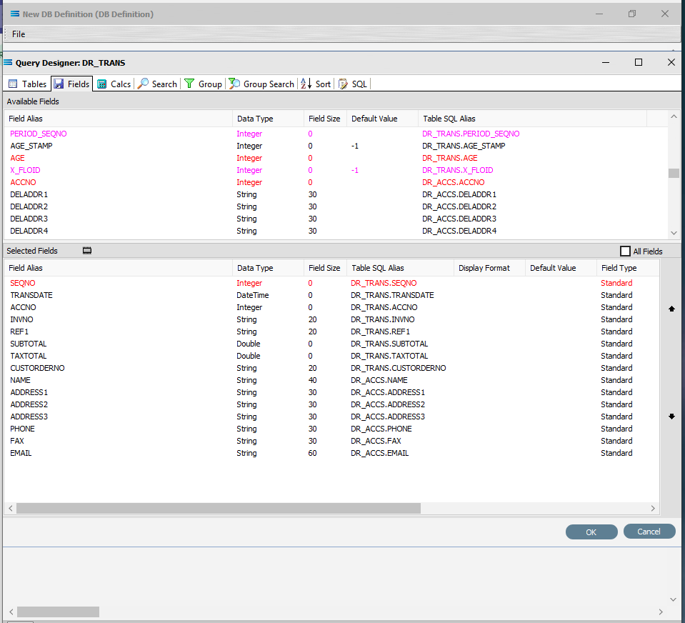
Move to the Fields tab, and add the following fields to the query by double-clicking on them:
SEQNO (sequence number)
TRANSDATE (transaction date)
ACCNO
INVNO (invoice number)
REF1
SUBTOTAL
TAXTOTAL
CUSTORDERNO. CUSTORDERNO is located well down the list. Click on Field Alias to sort. In alphabetic sequence.
As you select fields from the Available Fields pane, they will appear in the Selected Fields pane, and disappear from the Available Fields pane.
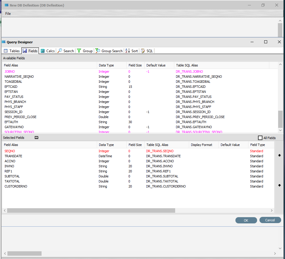
As already observed in previous tutorials, if you select the wrong field, simply double-click on it as a selected field and it will be de-selected.
The fields are colour coded in the Query Designer. RED indicates that the field is either calculated or is an automatically generated IDENTITY type such as SEQNO. PINK indicates that the field does not allow null values.
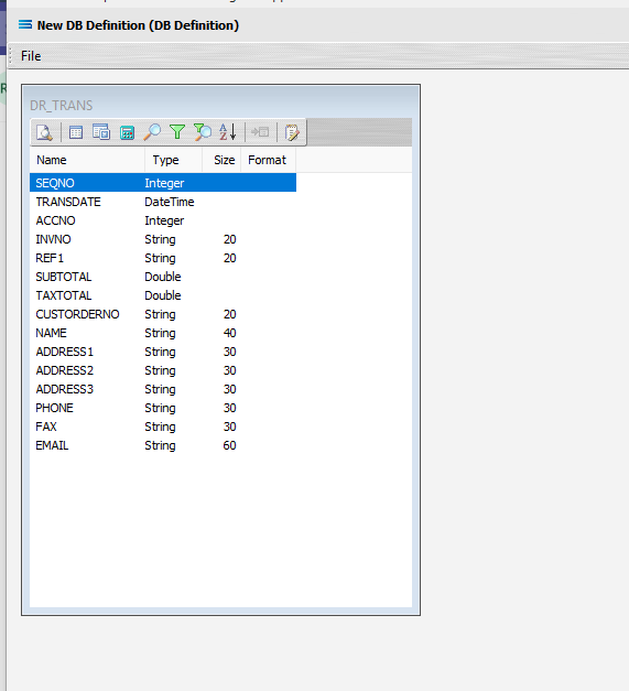
Click OK at the bottom-right of the Query Designer to save the dataview and return to the definition canvas. The configured dataview will display, listing all of the fields that were selected in the previous step. This box can also be expanded as required.
Join Another Table To Dataview Query
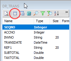
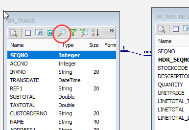
Now the table DR_ACCS is to be joined to this current DR_TRANS dataview. The DR_ACCS table holds the additional details about the customers that are required to produce the invoice file. Click on the Tables toolbar button on the DR_TRANS dataview to go to the Tables tab in the Query Designer.
Find and double-click on the DR_ACCS table to add it to the current query. The Join Table window will immediately pop up.
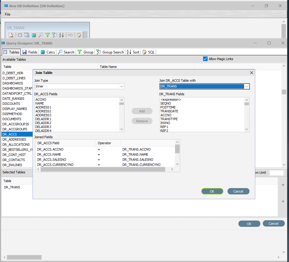
At the very bottom of this Join Table pop-up window, there is a section labelled as Joined Fields, with a list of all of the available fields that can be found in the DR_ACCS table listed under the DR_ACCS Field column. You will notice that all of the field names are prefixed by the name of the table, with a full-stop as a separator.
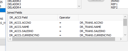
Remove all of the fields listed except for DR_ACCS.ACCNO by double-clicking on each field name in turn, or by highlighting the field name and then clicking on the Remove button. This button will be greyed out until a field is highlighted.
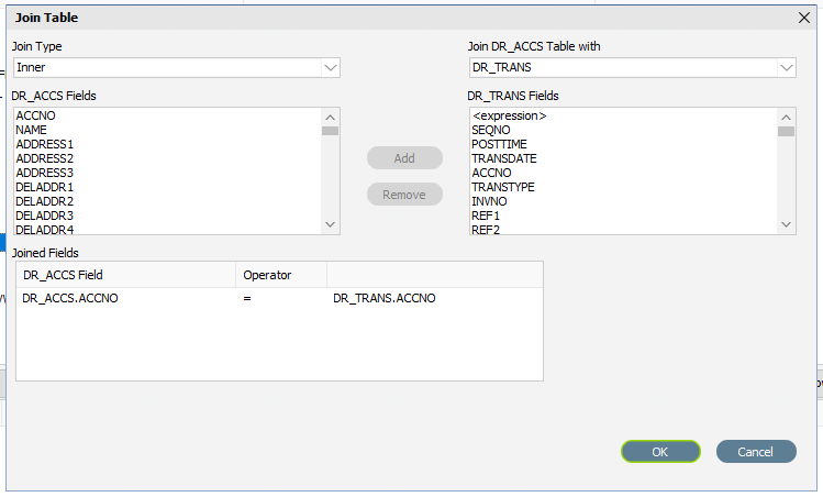
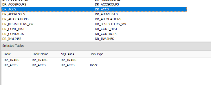
Click OK to save the selection and close the window. Having returned to the Query Designer window, you will see the table DR_ACCS appear under the Selected Tables area with a Join Type of Inner.
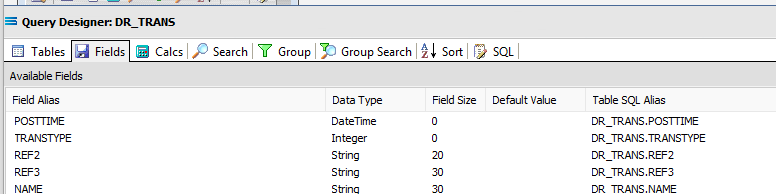
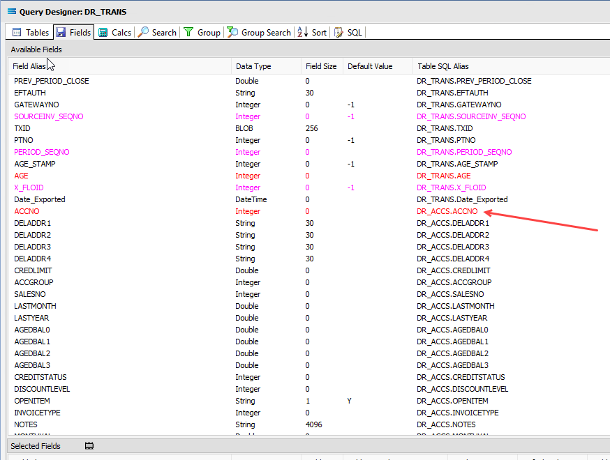
Move to the Fields tab. All of the fields from the DR_ACCS table have been appended to the Available Fields list, and are identified by the name listed under the very right-hand Table SQL Alias column, with the table name prefixing the field name. The table name and field name are separated by a full stop.
Scroll down the list until to reach the fields from the DR_ACCS table.
Add the following fields from DR_ACCS to the query by double-clicking on them to add them to the Selected Fields pane:
NAME
ADDRESS1
ADDRESS2
ADDRESS3
PHONE
FAX
EMAIL
You will see the fields as now selected, are easily identifiable by their Table SQL Alias.
Save the two-table query by clicking OK on the bottom right of the window, and return to the definition canvas. The configured dataview will display, listing all of the fields that were selected - from both tables.
Add Another Dataview Query
Add another DB Dataview - click on the File menu in the top left corner, and choose New (or use the Ctrl+N). The New Items window will open and only one item called DB Dataview will be displayed.
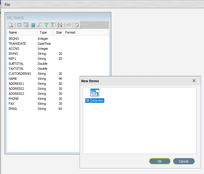
Click OK to add DB Dataview. The Query Designer window will open.
Scroll down the available tables to DR_INVLINES (Debtor Invoice Lines) and double-click to select it. The selected table will appear in the lower pane, but will also stay in the Available Tables pane.
Move to the Fields tab, and add the following nine fields to the query by double-clicking on them:
SEQNO (sequence number)
HDR_SEQNO (invoice header sequence number)
STOCKCODE
DESCRIPTION
QUANTITY
UNITPRICE
LINETOTAL_TAX
LINETOTAL
LINETOTAL_INCTAX
SEQNO, LINETOTAL, and LINETOTAL_INCTAX will display as RED. As you select fields from the Available Fields pane, they will appear in the Selected Fields pane, and disappear from the Available Fields pane.
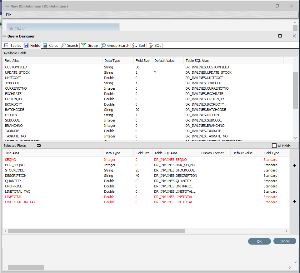
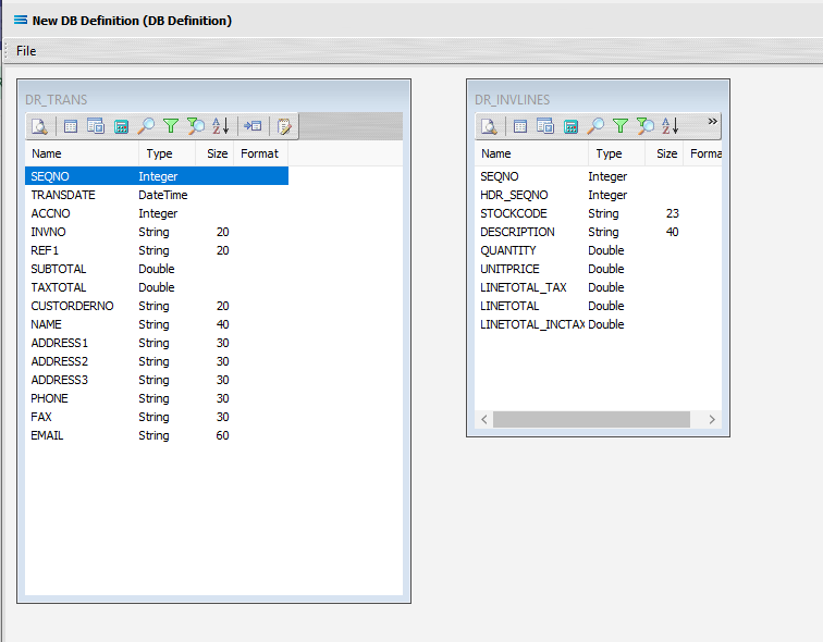
Click OK at the bottom-right of the Query Designer to save the dataview and return to the definition canvas. Both configured dataviews will display - one named DR_TRANS and one named DR_INVLINES.
Link The Datasets
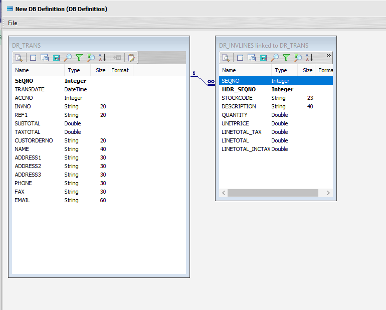
We want to link these together, so we will add a relationship between the two datasets by dragging the HDR_SEQNO field from the DR_INVLINES dataview and dropping it onto the SEQNO field of the dataview DR_TRANS. The drag-and-drop label will tell you when you are hovering over the correct field and can release the cursor.
Look out for “Link detail DR_INVLINES.HDR_SEQNO to master DR_TRANS. < >”. The field name within the diamond brackets is the field that will be linked to.
If you accidently drag‑and‑drop and link the wrong fields together, click on the diagonal link line so that it is highlighted in CYAN, and press Delete. Then simply re-link the fields across the datasets.
If you already have established a link between the datasets using this drag-and-drop action, any additional drag-and-drop link will replace the existing link.
To achieve any additional links, use the LINK toolbar icon in the child dataset, and create your multiple links this way.
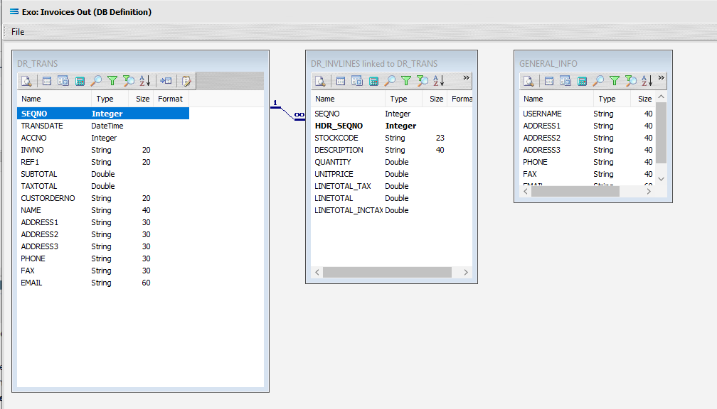
Three things will happen. DR_INVLINES will be renamed to DR_INVLINES linked to DR_TRANS. A one‑to‑many relationship link will appear between the two dataviews - the “single” link pointing at SEQNO in DR_TRANS, and the many pointing at HDR_SEQNO in the renamed dataview DR_INVLINES linked to DR_TRANS. These two linked fields will also be highlighted in bold text.
You have come so far, so for peace of mind, you can save your progress so far by selecting File Close, and then Save the DB Definition. To continue, simply click in the definition Exo: Invoices Out again to open it, and select Design to open the definition canvas. Your two datasets should display as above.
Add Another Dataview Query
In this tutorial, a third dataview now needs to be added. Click File New, click OK to add a DB Dataview.
In the Query Designer, scroll down and select the GENERAL_INFO table by double-clicking on it in the Available Tables list. It will appear under Selected Tables.
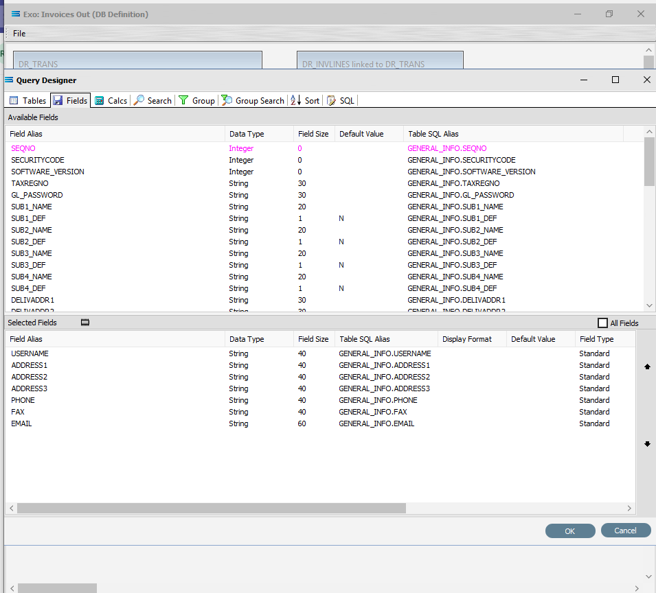
Move to the Fields tab. Add the following fields by double-clicking on each of them in turn:
USERNAME (company name)
ADDRESS1
ADDRESS2
ADDRESS3
PHONE
FAX
EMAIL
Click OK at the bottom-right of the Query Designer to save the dataview and return to the definition canvas. A third unlinked dataview called GENERAL_INFO will appear on the canvas.
Now we want to add some criteria. You can click the Search tab on the DR_TRANS dataview to open the Query Designer window on the Search tab.
Or get to the same place by simply clicking on the Tables tab for the dataview.
And then when the Query Designer window opens, move to the Search tab. Expand the window as required.
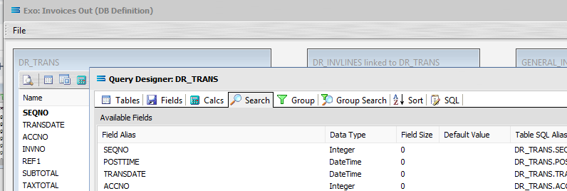
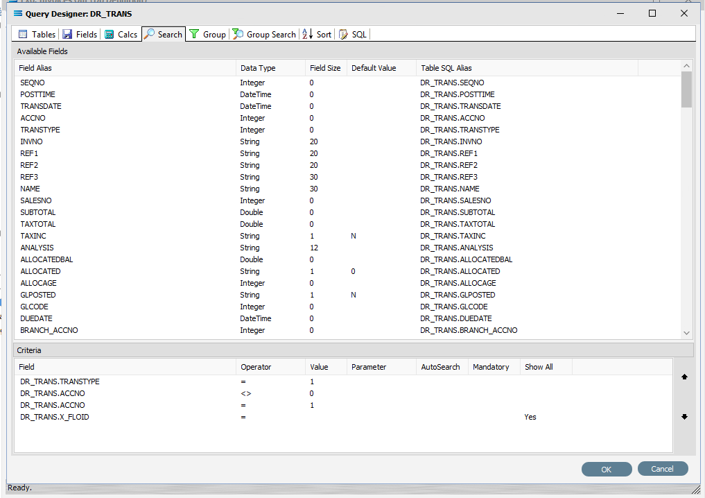
The upper pane shows the Available Fields, under the heading of Field Alias. This table holds the data for payments as well as invoices, so as we only want to select records pertinent to invoices, we add the criteria here. To the right of the field name in the lower Criteria pane, there are several extra fields, including Operator and Value. To select a field, double-click on it in the Available Fields list. You can click on an individual field more than once – it will not disappear from the available fields list once selected. The Operator can be selected from the drop-down list.
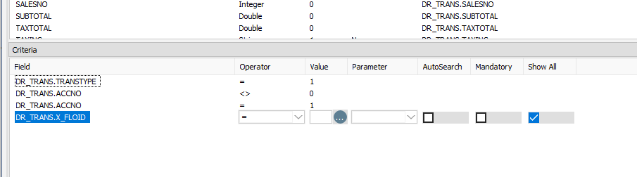
Use Tab to move from one column into another, or simply click out of the column to move across. The field name will appear in the lower Criteria pane, prefixed by the table name, and separated by a full-stop. Where a choice is offered such as with Operator, click on the drop-down sign to see available selections, and then select the appropriate one. Click on the following fields to move them to Criteria, and add the following selection criteria:
TRANSTYPE = 1 (to only select invoices -“1” means an invoice. Operator is an equals sign = and Value is 1)
ACCNO <> 0 (do not include cash account transactions)
ACCNO = 1 (currently only select transactions for account #1)
X_FLOID = Show All (tick Show All so that any criteria will be ignored at this stage)
Click OK at the bottom-right of the Query Designer to save the dataview and return to the definition canvas.

Close the definition canvas by selecting Close from the File menu. You will return to the Exo: Invoices Out definition window. Click Save to save and close the module.
The DB Definition named Exo: Invoices Out will now appear in the structure tree under Configuration > Components > Data Definitions > DB Definitions.
What the data is - Creating file definitions
The File Definitions module is used to design the structure of the files that are read from, or written to, the Statelake configuration. This tutorial illustrates the use of a multi‑tier dataset for the destination.
Designer will already be open. If not, open the Statelake module Designer for the selected configuration. An expanded structure tree is displayed on the left side of the screen.
Create File Definition
Follow the path Configuration > Components > Data Definitions > FIle Definitions. Right‑click on File Definitions and choose New from the drop-down list.
New File Definition appears in the structure tree. In the New File Definition window the following information is to be entered under the General tab.
File Type – select XML File.
File Definition Name – the default is New File Definition. Enter the definition name of the source file, as specified during the creation of the File Connection. In this tutorial it is Training: Invoice.
DB Connection – right-click anywhere in the DB Connection box, select Add then select MYOB Exo.
File Connection - select Training: Invoice from the pull-down list.
Disable Automatic String trim – leave with the default tick as set.
XSD Schema – either click the 3-dot ellipse to navigate to the directory where the schema files were copied and select Invoice.xsd by clicking on Open or enter the path name as <DefaultDir>\Training\Invoice.xsd.
When working with XML files, Statelake will always require schema files (XSD), not only to define the structure of the file, but also for validation purposes when reading from, or writing to, and XML file.
g. Resolve Imported/included schemas (recommended) – leave as ticked.
h. All other fields and tick boxes are to be left as defaulted.
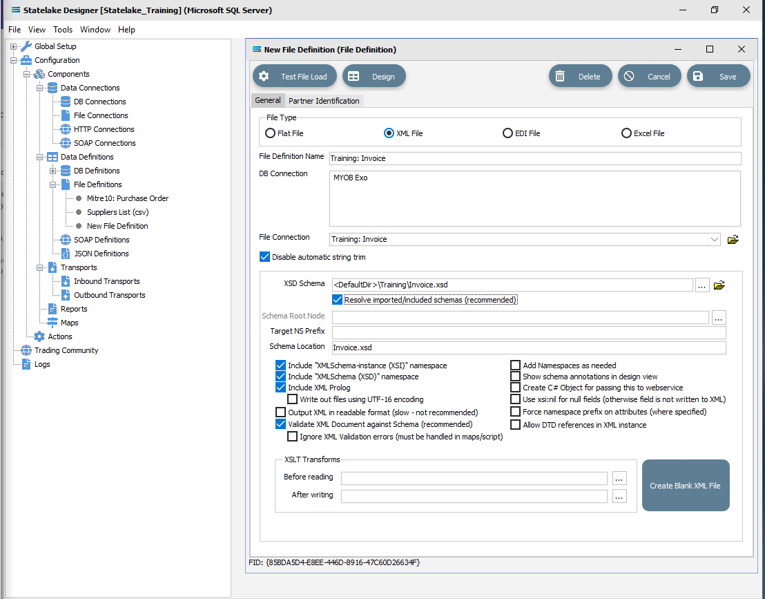
Click Design in the top left of the window.
Create File Dataview Query
A blank definition designer canvas will display. To start creating your file, click on the File menu in the top left corner, and choose New (or use the Ctrl+N).
The New Items window will open and two options called XML Dataview and DB Dataview will be displayed.
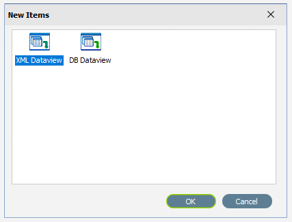
Select XML Dataview and click OK to add a new XML Dataview. The XML File Designer window will open. Expand this window if required, to ensure that the Available Records and Selected Record panes are both displayed fully.
The Records tab may automatically populate some records or elements. These are read from the schema file that you identified on the initial window.
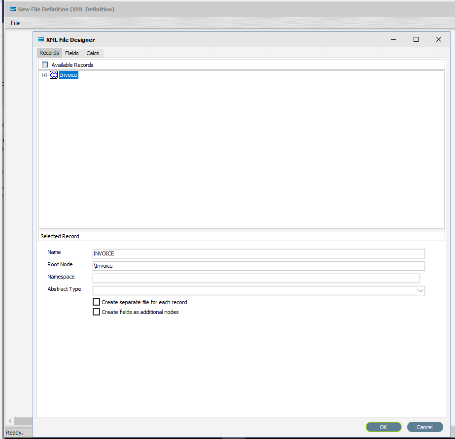
There are three tabs – Records, Fields and Calcs. In this tutorial, the Records tab will display Invoice in the Available Records pane schema tree. If there are multiple entries, scroll down until Invoice is highlighted and double-click on it to select. Invoice is the Root Node.
The Name and Root Node fields in the lower Selected Record pane will be automatically populated. Name will display as INVOICE. Root Node will display as \Invoice.
Root Node in this context is the parent element or file identifier for the group of fields and records that you are adding to this dataview. You will see that the path to the fields will be constructed based on the Root Node you specified.
b. All other fields and tick boxes are to be left as the set default.
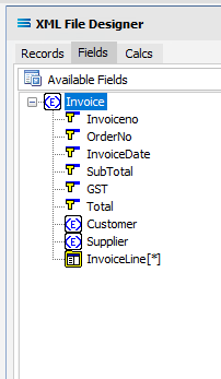
Click on the Fields tab. If it has not already been expanded, then click on the plus to expand Invoice in the Available Fields pane.
The structure in the schema file Invoice.xsd determines how these field relationships are handled within this XML File Definition.
There is a symbol to the immediate left of the field name. A BLUE <E> signifies that the item is a non-repeating complex element (a record). A folder icon identifies a repeating complex element (record). A YELLOW T indicates a simple element (a field),
The top level in the file structure tree is referred to as the Root Node - the name given to the envelope that holds the group of source records. It is the start of the structure tree. In this tutorial, this is the name given to this group of invoices.
The elements Customer and Supplier are nodes that branch off the Root Node. These are datasets or groups of records in their own right with their own sets of fields.
The asterisk (*) at the end of the field name means that you can have more than one of these fields in a single record. There is no limit.
A RED A at the end of the field name identifies the field as an attribute.
Click on the <E> symbol beside Customer and Supplier to expand these groups, to show the fields within this record grouping. Expand the window or drag the separator bar between the upper and lower panes down if required.
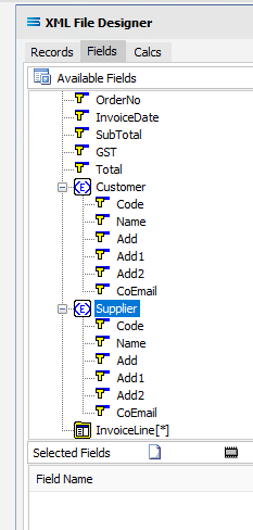
Now click on every field under Invoice, Customer and Supplier to add them to the Selected Fields pane. Do not however, click the elements themselves (those with a <E> symbol prefix). And do not select the folder InvoiceLine, as this will be dealt with in the next step. We want all of the fields, but not their “wrappers”. You will see that every field once selected will be prefixed with the element name and an underscore as a location tag. For instance, the first field selected will be Invoiceno within the Invoice “wrapper”. It will appear in the Selected Fields pane as Invoice_Invoiceno.
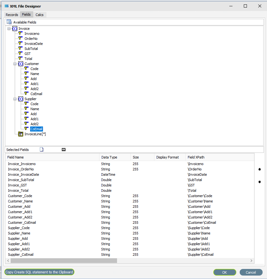
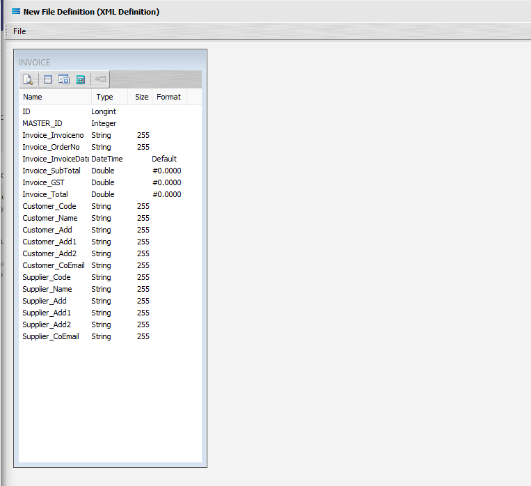
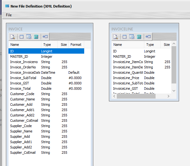
Click on the the OK button to save and close the window. You will return to the New File Definition canvas and a definition window named INVOICE will display. Expand this window as desired.
Create 2nd Dataview Query
Create another XML Dataview for the node InvoiceLine by clicking on the File menu in the top left corner, and choose New (or use the Ctrl+N). Select XML Dataview and click OK to add a new XML Dataview.
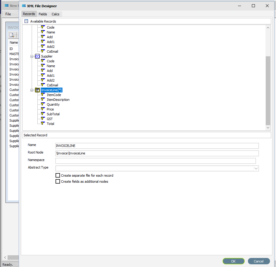
The XML File Designer window will open on the Records tab and will display the expanded selection of Invoice, Customer and Supplier as previously displayed. Double-click on InvoiceLine to select it as the Root Node.
The Name and Root Node fields in the lower Selected Record pane will be automatically populated. The Name will now say INVOICELINE. The Root Node will now say \Invoice\InvoiceLine.
All other fields and tick boxes are to be left as the set default.
Move to the Fields tab and click on the plus to expand InvoiceLines if it is not already expanded. Add all of the fields by double‑clicking on them. Do not select InvoiceLines itself.
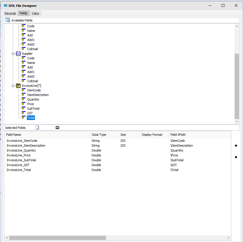
Click the OK button to save and close the window. The New File Definition canvas will display the two definitions INVOICE and INVOICELINE, being the names given to each Root Node.
Link The Datasets
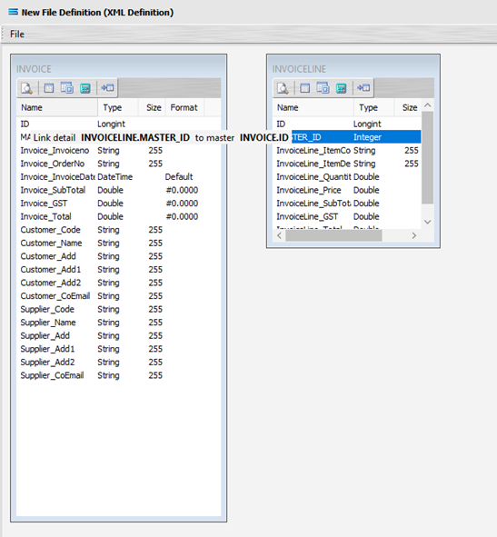
To link the two together, we add a relationship between the two datasets by dragging the MASTER_ID field from the INVOICELINE dataview and dropping it onto the ID field of the dataview INVOICE.
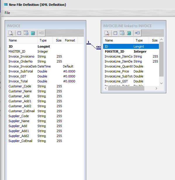
You will notice the same linking behaviour as previously experienced. Three things will happen. INVOICELINE will be renamed to INVOICELINE linked to INVOICE. A one‑to‑many relationship link will appear between the two dataviews - the “single” link pointing at ID in INVOICE, and the many pointing at MASTER_ID in the renamed dataview INVOICELINE linked to INVOICE. These two linked fields will also be highlighted in bold text.
Click on the Records tab of the INVOICE dataview.
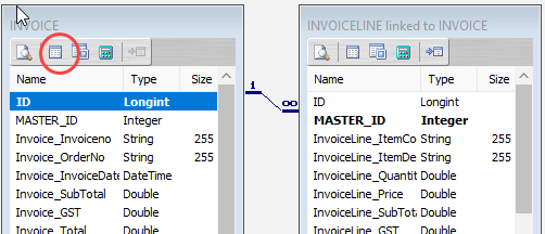
Then click in the tick box Create separate file for each record.
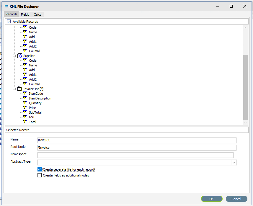
Click the OK button to save and close the window.
Close the definition canvas by selecting Close from the File menu. You will return to the New File Definition window. Click Save to save and close the New File Definition module and the definition Training: Invoice.
The File Definition named Training: Invoice will now appear in the structure tree under Configuration > Components > Data Definitions > File Definitions. You have now successfully created another file definition for an XML file type with a multi‑tier dataset.
What To Do With The Data - Creating Maps
You have skillfully created two XML definitions for this tutorial. Now the Map is to be created.
Designer will already be open. If not, open the Statelake module Designer for the selected Statelake_Training configuration. An expanded structure tree is displayed on the left side of the screen.
Create The Map
Follow the path Configuration > Components > Maps. Right‑click on Maps and choose New from the drop-down list.
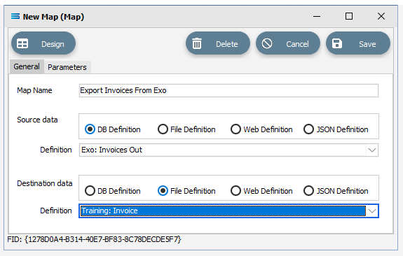
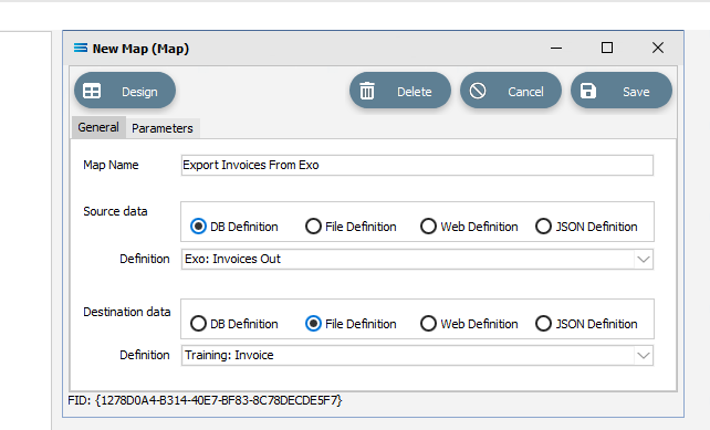
A New Map item is added to the tree. The New Map window contains two tabs - General and Parameters. The Parameters tab allows you to set other options, but for training purposes, we will be dealing with just the General tab. The following information is to be entered for the main map.
Map Name – for this tutorial the name will be Export Invoices From Exo.
Source Data – highlight the DB Definition radio button.
Definition – select the DB Definition that was created for this configuration called Exo: Invoices Out from the pull-down list.
Destination Data – highlight the File Definition radio button.
Definition – select the File Definition that was created for this configuration called Training: Invoice from the pull-down list.
Open The Map
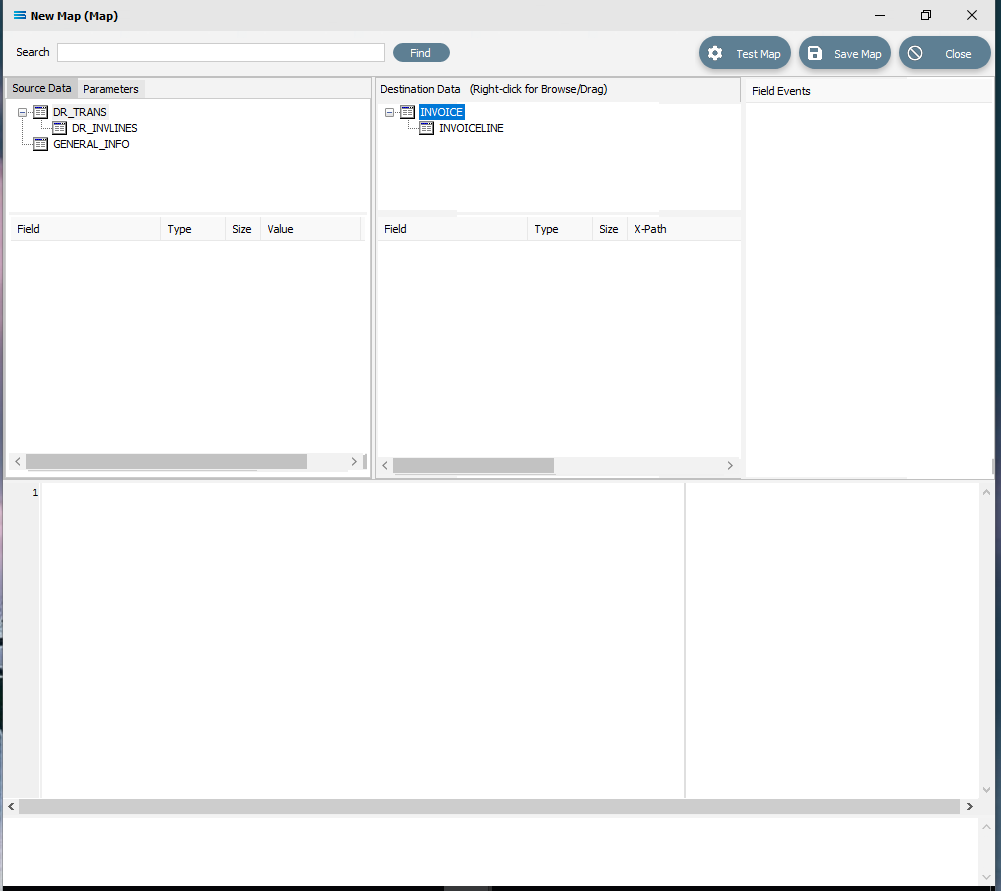
Click the Design button to open the map designer window New Map. You will now be familiar with the layout of the New Map window.
You will see under Source, the tables DR_TRANS and GENERAL_INFO. And under Destination, the table INVOICE. Click the plus beside DR_TRANS in the Source pane to expand, and click on the plus beside INVOICE in the Destination Data pane.
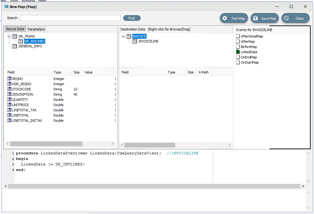
In this tutorial we will link the source dataset table DR_TRANS to the destination INVOICE dataset by dragging and dropping DR_TRANS onto INVOICE. A successful drag-and-drop will produce a LinkedDataEvent code in the Scripting Area.
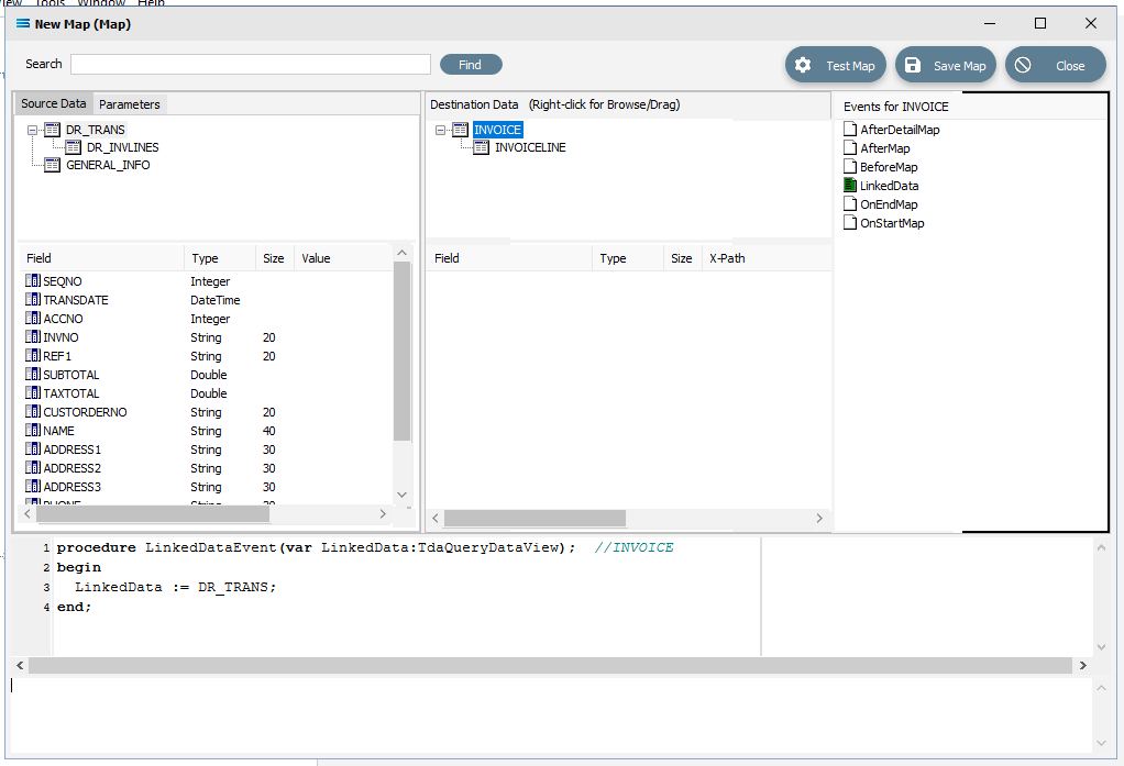 Close up of the code.
procedureLinkedDataEvent(varLinkedData:TdaQueryDataView);// INVOICEbeginLinkedData := DR_TRANS;end;And we will link the table DR_INVLINES in Source Data, to INVOICELINE in the Destination Data area by dragging and dropping DR_INVLINES onto INVOICELINES. A successful drag-and-drop will produce the following LinkedDataEvent code in the Scripting Area.
 Close up of the script.
procedureLinkedDataEvent(varLinkedData:TdaQueryDataView);// INVOICELINEbeginLinkedData := DR_INVLINES;end;Click on DR_TRANS in Source Data and INVOICE in Destination Data to make those your current selected tables.
Link The Fields
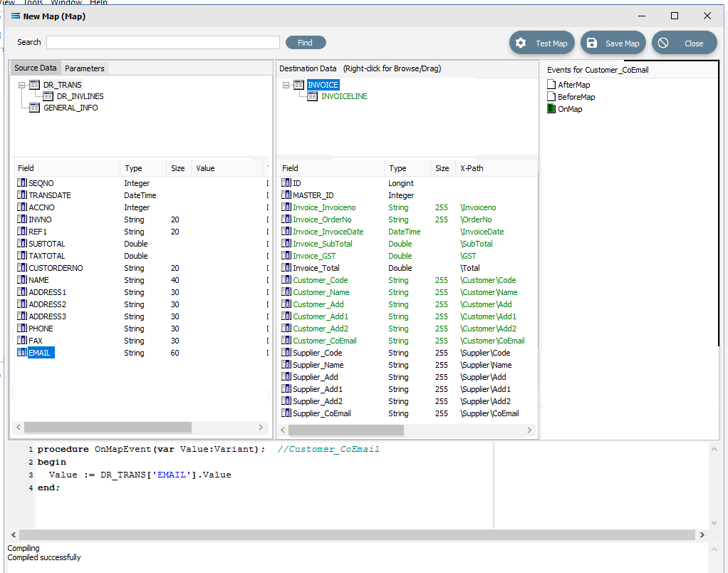
Now link the fields that are listed below using the same drag-and-drop technique. Drag the fields from the Source Data onto the Destination Data field. Each successful action will automatically generate OnMapEvent code in the Scripting Area, such as this following example for DR_TRANS.INVNO to Invoice_Invoiceno. The field in the Destination Data pane will change to GREEN.
procedureOnMapEvent(varValue:variant);// Invoice_InvoicenobeginLinkedData:= DR_TRANS['INVNO'].Valueend;DR_TRANS.INVNO to Invoice_Invoiceno
DR_TRANS.CUSTORDERNO to Invoice_OrderNo
DR_TRANS.TRANSDATE to Invoice_InvoiceDate
DR_TRANS.SUBTOTAL to Invoice_SubTotal
DR_TRANS.TAXTOTAL to Invoice_GST
DR_TRANS.ACCNO to Customer_Code
DR_TRANS.NAME to Customer_Name
DR_TRANS.ADDRESS1 to Customer_Add
DR_TRANS.ADDRESS2 to Customer_Add1
DR_TRANS.ADDRESS3 to Customer_Add2
DR_TRANS.EMAIL to Customer_CoEmail
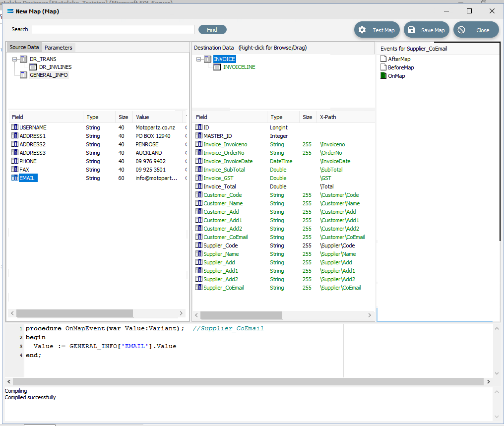
Click on the GENERAL_INFO dataset in the Source pane to make the current selection, and drag-and-drop the fields onto the INVOICE dataset in the Destination pane as below.
GENERAL_INFO.USERNAME to Supplier_Name
GENERAL_INFO.ADDRESS1 to Supplier_Add
GENERAL_INFO.ADDRESS2 to Supplier_Add1
GENERAL.INFO.ADDRESS3 to Supplier_Add2
GENERAL_INFO.EMAIL to Supplier_CoEmail
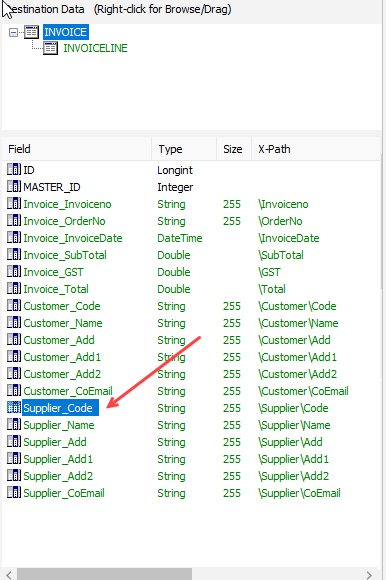
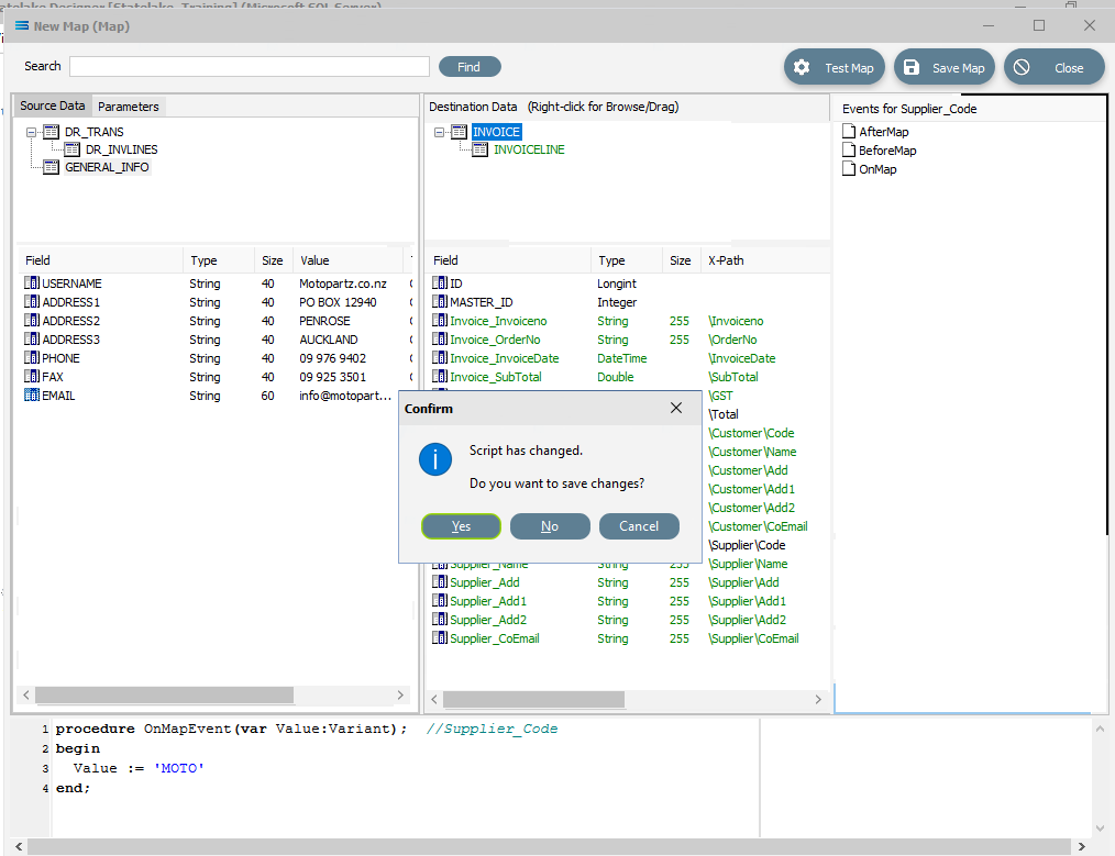
Click on the Supplier_Code field in INVOICE to highlight it. This field is near the bottom of the list and has not been linked.
Click anywhere in the Scripting Area panel and Statelake will generate code for that field, as below.
procedure OnMapEvent(var Value:Variant); //Supplier_Codebegin Value := end;Append to the third line and type ‘MOTO’ (single quote MOTO single quote) immediately after the Value :=, to set this to a static value.
procedure OnMapEvent(var Value:Variant); //Supplier_Codebegin Value := 'MOTO'end;Click back on the Supplier_Code field and you will be prompted to save your changes, so click Yes.
After entering the code as below, you can right-click anywhere in the Scripting Area and select Test Compile to verify that there are no errors and that the code has compiled successfully. The field colour will change to GREEN if the code has no error, but RED if there is an error with the script. Correct any script code errors and re‑test until the code is accepted.
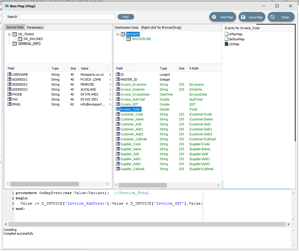
Click on the field INVOICE.Invoice_Total to highlight it. This field has also not been linked as yet, and only a 1 will be displayed in the Scripting Area.
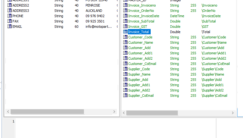
Click anywhere in the Scripting Area panel to automatically generate the OnMapEvent code. Append the third line to read: Value := D_INVOICE[‘Invoice_SubTotal’].Value + D_INVOICE[‘Invoice_GST’].Value;
The D_ simply stands for destination, so it refers to the INVOICE dataset in Destination Data. Click back on the Invoice_Total field and you will be prompted to save your changes, so click Yes. If there is an error with the code, then the compile test will fail - correct the code and try again until your compile is successful.
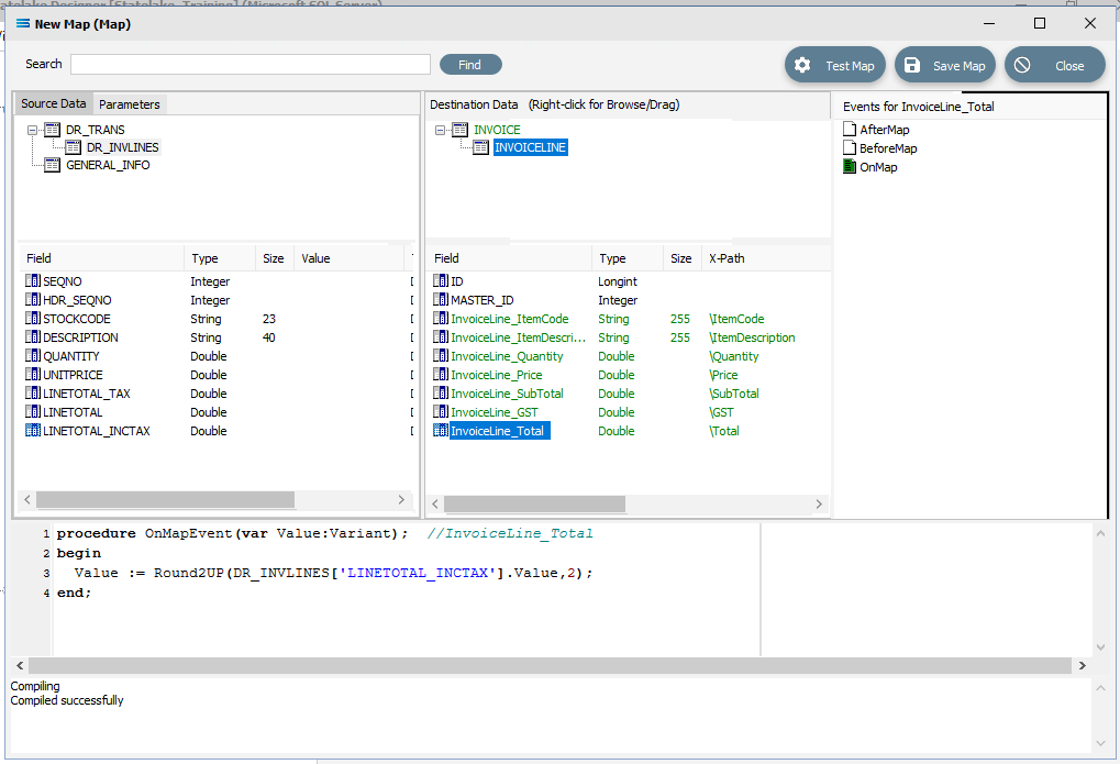
Click on DR_INVLINES in Source Data, and on INVOICELINE in Destination Data to make these datasets the current selection.
Now map the following fields using the same drag-and-drop procedure:
DR_INVLINES.STOCKCODE to InvoiceLine_ItemCode
DR_INVLINES.DESCRIPTION to InvoiceLine_ItemDescription
DR_INVLINES.QUANTITY to InvoiceLine_Quantity
DR_INVLINES.UNITPRICE to InvoiceLine_Price
DR_INVLINES.LINETOTAL to InvoiceLine_SubTotal
DR_INVLINES.LINETOTAL_TAX to InvoiceLine_GST
DR_INVLINES.LINETOTAL_INCTAX to InvoiceLine_Total
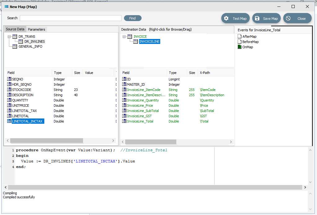
Click on InvoiceLine_Total. Click into the Scripting Area and alter the script by adding a function to round the value to the nearest cent. Line 3 of the script becomes: Value := Round2UP(DR_INVLINES[‘LINETOTAL_INCTAX’].Value,2);
Click on InvoiceLine_Total to save the script.
Save the Map and commit all of the mapping and scripting by clicking Save Map in the top right corner. Select OK to close the successful save message, then click on the Close button to close the map designer window.
To commit all the mapping and scripting, click Save to save and close the mapping module.
The Map named Export Invoices From Exo will now appear in the structure tree under Configuration > Components > Maps.
Test The Map
Now test the Map to ensure it is working:
Open the Maps module again by clicking on Export Invoices From Exo, and click on the Design button.
The Export Invoices From Exo map designer screen will display, with the Source data DR_TRANS and GENERAL_INFO showing, and INVOICE showing under Destination Data. INVOICE will be displayed in GREEN.
Click on Test Map in the top right corner of the screen, to execute the map in memory and generate a processing log which is then presented in a preview pane. If there is no data selected, then the log will have a pale YELLOW background.
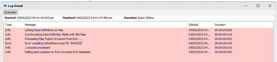
If this occurs check your definitions or your script code, change whatever is incorrect, and try the test again. Outright errors will have a dark PINK background.
But with a successful test, the background will be pale GREEN.
Close the pop-up preview of the log by clicking on the X, and the XML definition query Training: Invoice will be displayed on the canvas, including showing the link between INVOICE and INVOICELINE. Click on the Preview button on either dataset to view the list of all the processed records.
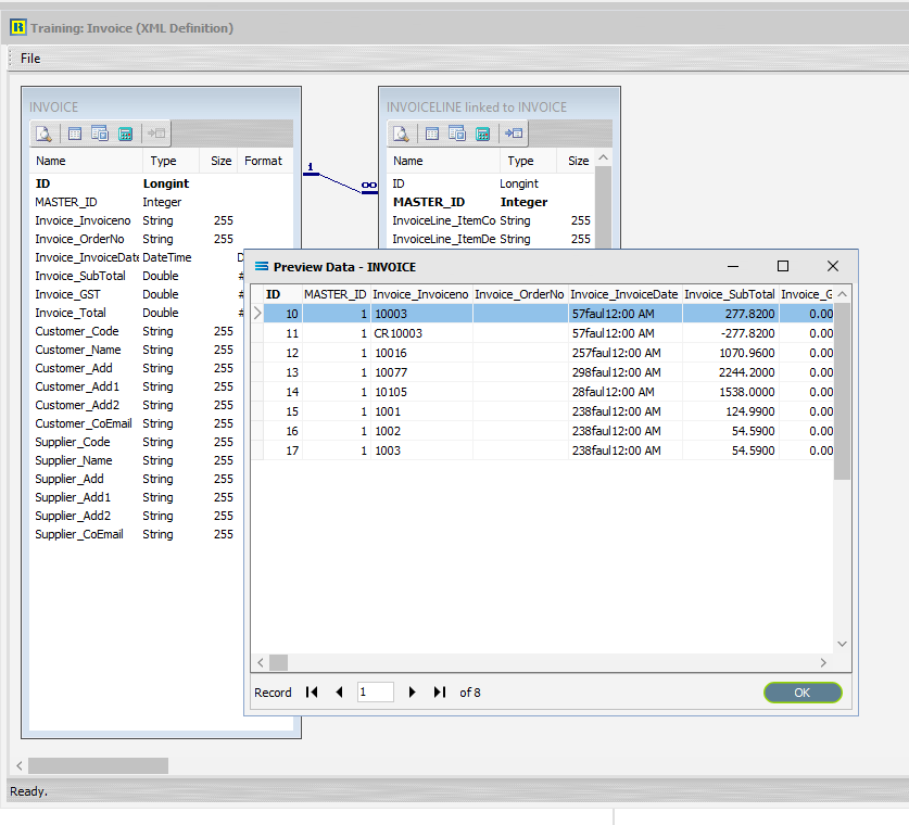
Click the X to close the Preview Pane.
You can only have the preview of one dataset open at any time.
Select File Close on the canvas, the Close button on the map designer screen, and the Cancel button on the Export Invoices From Exo map entry window.
The Map has now been successfully configured, although no actual database activity has been generated.
What Action To Take - Creating An Action
The next step is to create an Action. In this tutorial we will automatically create the Action from the Map.
Designer will already be open. If not, open the Statelake module Designer for the selected configuration. An expanded structure tree is displayed on the left side of the screen.
Create The Action Automatically
Follow the path Configuration > Components > Maps. Right‑click on the map you have just created Export Invoices From Exo, and choose Create Action from the drop‑down list. An Action of the same name will be created and opened, and all the relevant components will be automatically added to this Action.
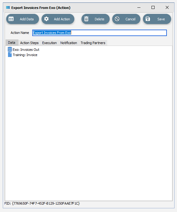
There is no need to do anything with this window, except select Save on the top right corner to close the module.
The Action named Export Invoices From Exo will now appear in the structure tree under Configuration > Actions.
Amend The Action
In a live production situation, cancelled logs would not normally be retained. However, for the purposes of this tutorial we will change the notification default, so that all logs will be recorded and kept. Open the Action named Export Invoices From Exo, and move to the Notification tab.
In the section marked Save Log on the following execution statuses, make sure that all boxes are ticked – OK, Warning, Error, and Cancelled.
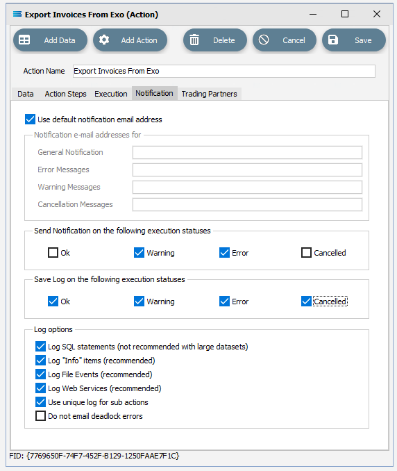
Select Save on the top right corner to save and close the module.
Run The Action
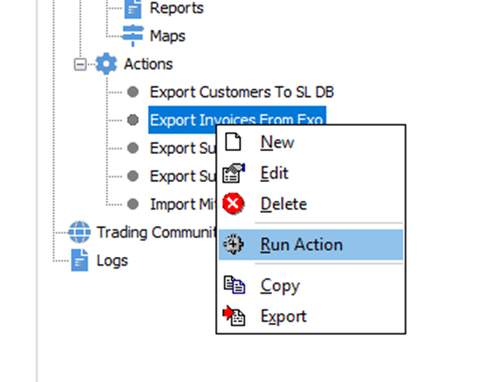
To run the Action, right-click on the Action named Export Invoices From Exo, then select Run Action.
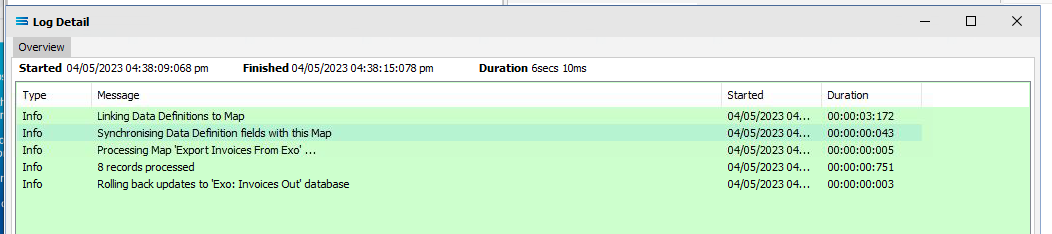
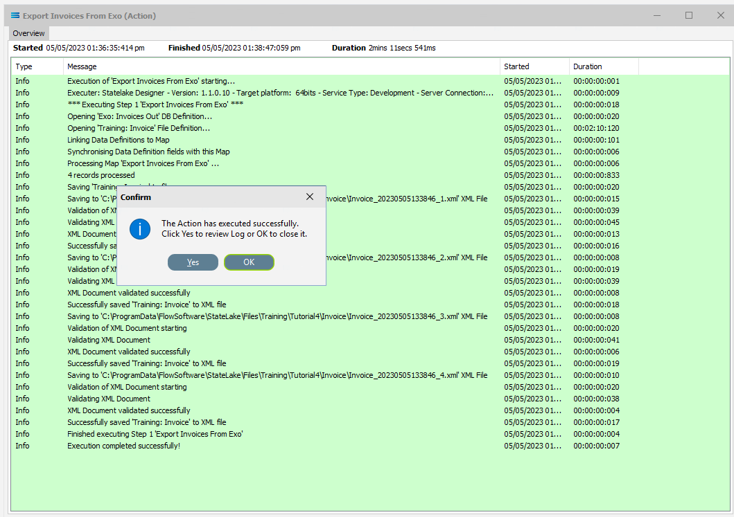
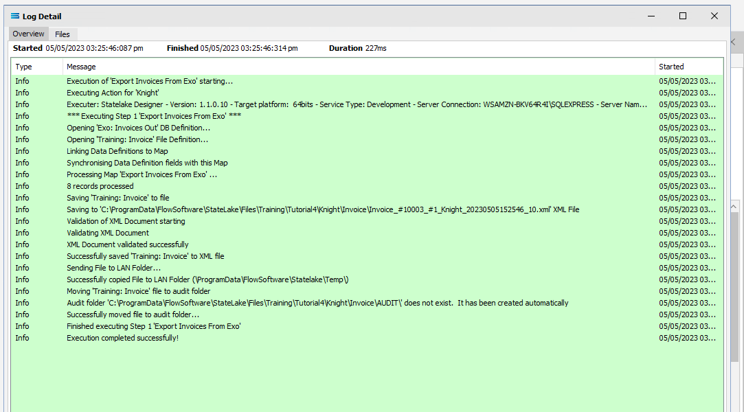
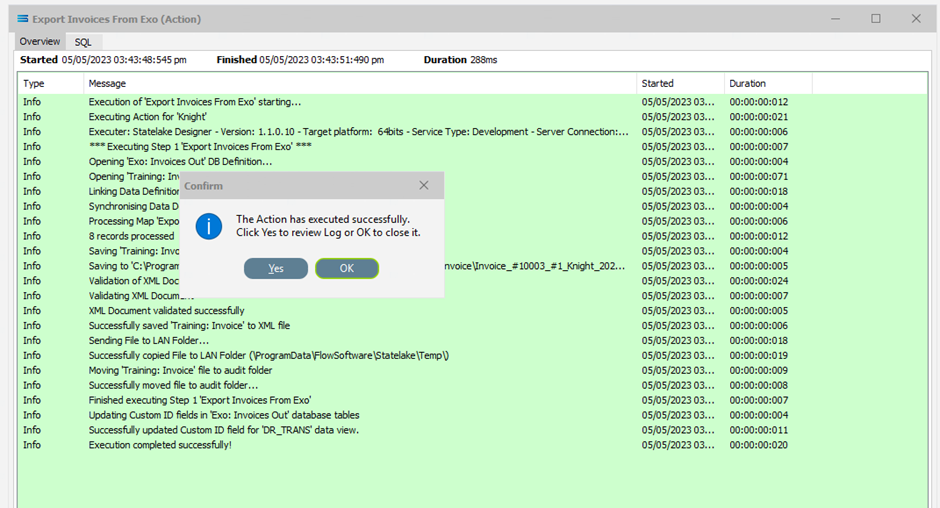
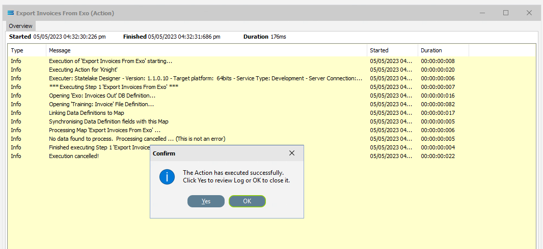
A window will pop-up showing the processing steps in a preview log, that will show the steps that were completed, how many records were extracted and processed, and where the destination file was saved. When the Action has been completed a status message will pop-up on screen indicating that processing is complete, and advising whether the process was successful or an error was encountered.
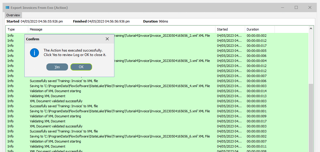
A successful Action will offer two choices – click Yes to review the log, or click OK to close the log without review. To close the log after review, click the X in the upper right corner.
Logs can be re-opened at any stage, and as many times as required. A review a Log from the Manage Logs module, double-click on the Log required. To drill into any line on a Log, double-click on the line to see more detail.
The process is now complete, all modules have been closed, and the structure tree will be the only item on the Designer screen.
The configuration for the basic process of extracting invoices into XML is complete. Well done !
Autosearch
Autosearch is an available option within the DB Definition that allows entry of the search criteria while running an Action. Rather than being entered as static values within the DB Definition as we have done, using this functionality not only allows for more flexibility, but also has the following benefits:
It separates the search criteria from the rest of the configuration, which could be useful for security reasons, or to allow for easy or frequent changes to the criteria.
It allows users to specify the value of the search criteria every time they run the Action.
The choice of the search criteria being can be based on the selected Trading Partner.
Configuring Autosearch
Designer will already be open. If not, open the Statelake module Designer for the selected configuration. An expanded structure tree is displayed on the left side of the screen.
Click on the DB Definition named Exo: Invoices Out to open it.
Click on Design to open the definition designer canvas.
Click on the Search tab on the DR_TRANS dataview. This opens the Query Designer window on the Search tab.
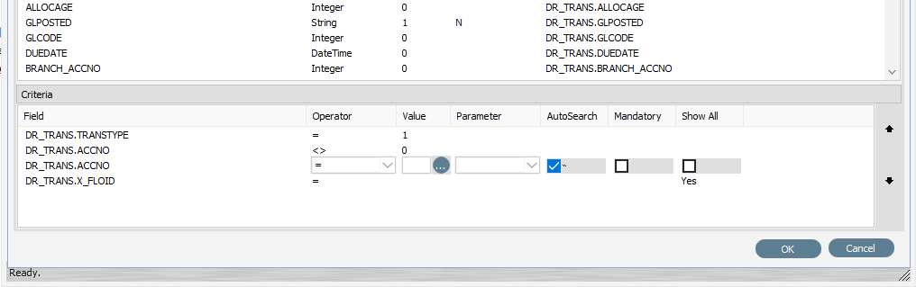
The field DR_TRANS.ACCNO appears twice in the Criteria pane – once with a value of <>0, and again with a value of =1. Remove the Value of 1 for the 2nd occurrence, and then tick the check box for AutoSearch on that line. The equals sign will stay visible as this is the default value.
Click on OK to save.
Select File Close on the definition canvas.
Select Save on the DB Definition window for Exo: Invoices Out to save this change.
Running Autosearch
You should currently be on the expanded structure tree home screen.
Click on Export Invoices From Exo under Actions to open it, then click on the DB Definition listed under the Data tab, called Exo: Invoices Out.
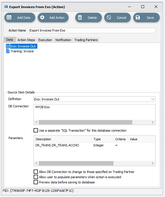
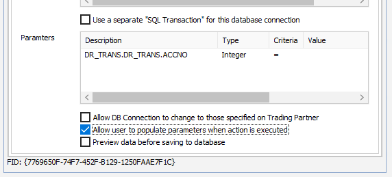
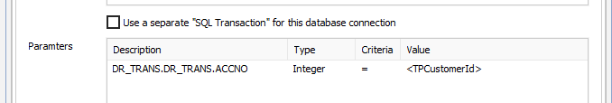
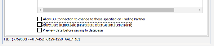
You will notice in the lower pane that appeared labelled Source Item Details, that DR_TRANS.ACCNO search criteria is now displayed under Parameters. This is now available for user input because of the change that you made in step 4 above in Configuring AutoSearch, where the AutoSearch button was ticked. Because AutoSearch was selected, the user is now allowed to enter the criteria here. Or alternatively, the search criteria can be entered when the Action is executed by ticking the checkbox labelled Allow user to populate parameters when action is executed. For the purposes of this tutorial, tick this box.
Click on Save to lock in the change you have made, and save and close the module.
Now right-click on the Action called Export Invoices From Exo, and select Run Action.
As well as beginning processing and displaying the log, once the process gets to the point where the field is required then a Provide Runtime Criteria Values window will pop‑up. Processing will suspend until you respond.
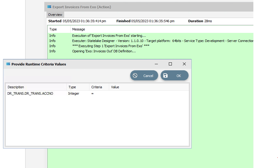
The Value column for DR_TRANS.DR_TRANS.ACCNO will be blank in this pop-up window. Click into the Value column, and enter your search criteria – in this case it will be the number 4. Enter 4, tab out of the column, then click OK.
The Action will resume processing, and you will see the displayed log file populate with additional processing lines.
Click on either Yes or OK to close the Action execution notification window and close the log.
Before closing the Log, if you take a note of these invoice XML file names and the folder that the files have been written to, you can navigate to the folder and view the contents for any one of the files just written. You will see they are all for customer #4, THE CAR JUNCTION.
Yes, it really is that simple.
Trading Community And Trading Partners
The Trading Community and Trading Partners features illustrates the flexible reusability and power of Statelake.
Let’s say that there are multiple customers of the company that we are using for this tutorial, who all accept and process the same type of style and format for digital invoices. The existing Action named Export Invoices From Exo can be used to send invoices to all of these customers.
With Trading Community, we can set up each of these customers under the Trading Partners umbrella, and use the one Action to generate and send invoices to all of them - without modification to the Action, and without the need to create separate Actions to accommodate each individual customer.
For this tutorial we will use three debtor accounts:
KNIGHT NICOL AUTOS (account number 1)
THE CAR JUNCTION (account number 4)
D & C PANELBEATERS (account number 5)
Create Trading Partners
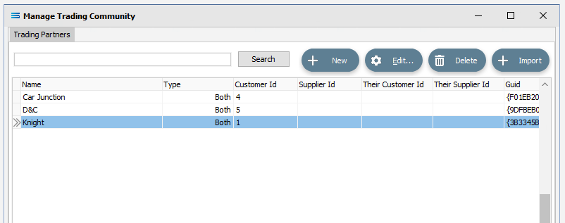
To add a new Trading Partner, click on the Trading Community item near the very base of the structure tree to open the window, and click New in the Manage Trading Community window.
The New Trading Partner window will pop-up. There are several tabs in this window. Under the General tab, the following information is to be entered:
Partner Name - for the first customer KNIGHT NICOL AUTOS, enter a meaningful but truncated version of their name. We will use Knight.
Partner Type – they are a customer so click the Customer radio button.
Your ID for them as customer – the customer number, so enter 1.
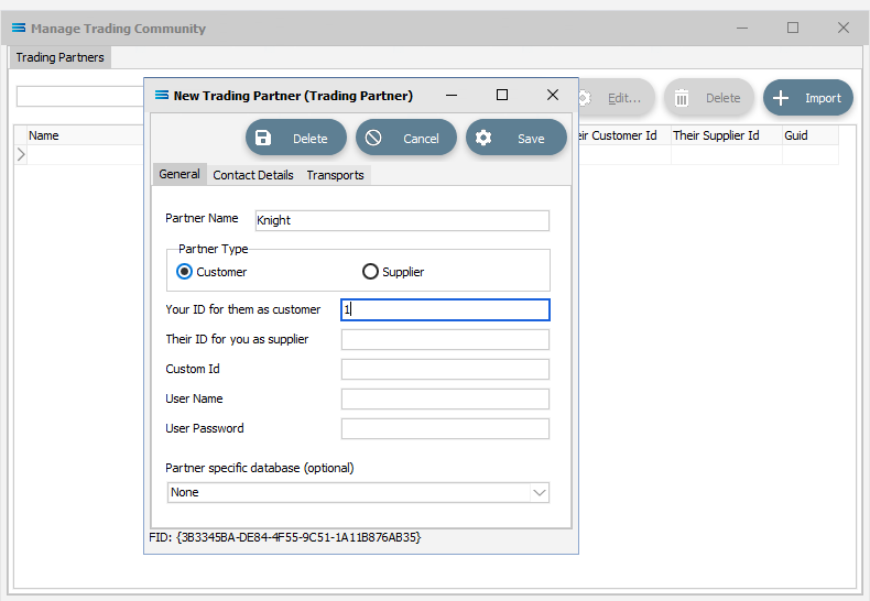
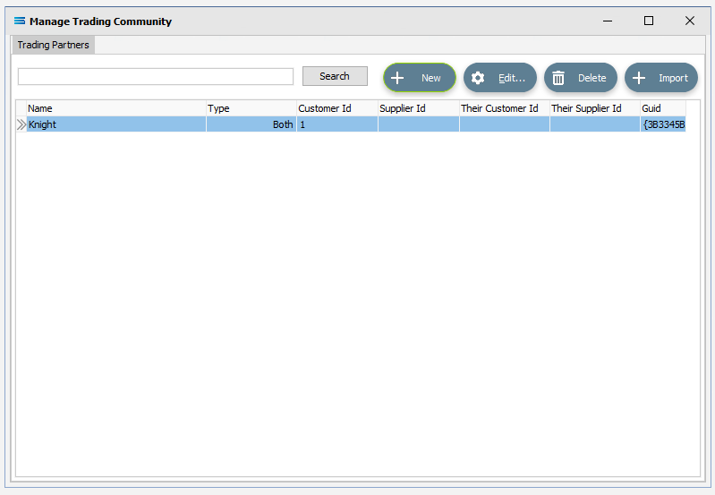
Select Save to save and close the window. On return to the Manage Trading Community window, you will see that a Trading Partner named Knight has been added to the list.
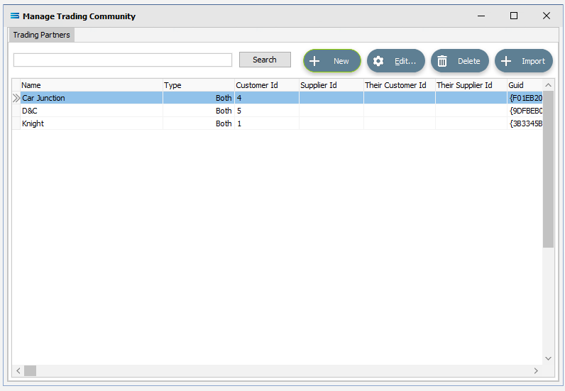
Repeat steps 2 through 4, adding THE CAR JUNCTION as Car Junction and ID #4, and adding D & C PANELBEATERS as D&C with ID #5. With each successful save, their names will be added to the list in the Manage Trading Partners window, sorted alphabetically.
There is no verification lookup on the Trading Partner window. If you make a mistake, then Statelake will not tell you with an error message. However, if you notice that you have made an error, simply highlight the Trading Partner line and click Edit and make your change. Else highlight the line concerned and click Delete. You can also delete the line by double-clicking on it.
Once the Trading Partners are on the list, they are automatically saved, so to close the Manage Trading Community window, just click the X.
How easy is that?
Using Trading Partners In An Action
To set up an Action to work with the Trading Partners, first open the Action that you are wishing to run.
Open The Action
For this tutorial, open the Action called Export Invoices From Exo.
Click on Exo: Invoices Out under the Data tab, to adjust the search criteria and take the Trading Partners into account. The lower section of the window will open into the Source Item Details pane.
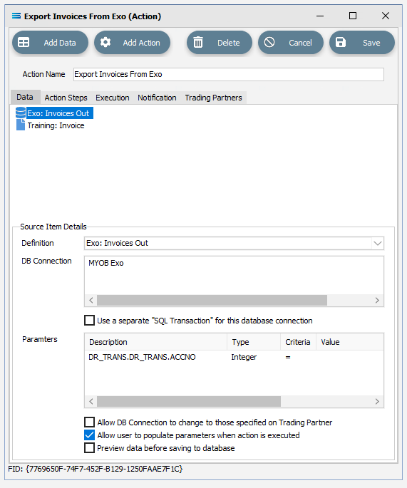
In the Value column for the Parameters for DR_TRANS.DR_TRANS.ACCNO, specify the Criteria to be <TPCustomerId>, including the angle brackets < and >. This is a partner tag that returns the Customer ID. Tab to get out of the column after input. The TP prefix to the tag, stands for Trading Partner.
So that the user is not requested to input any parameters, untick the checkbox below the Parameters section called Allow user to populate parameters when action is executed.
Select The Partners
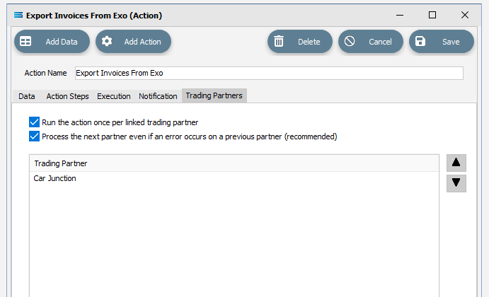
Move to the Trading Partners tab of the Action, and right-click anywhere in the white space within the Trading Partner pane. Select Add, and a window will pop-up that lists the partners that you created, displayed in alphabetic order. Each partner name also displays an internal ID sequence.
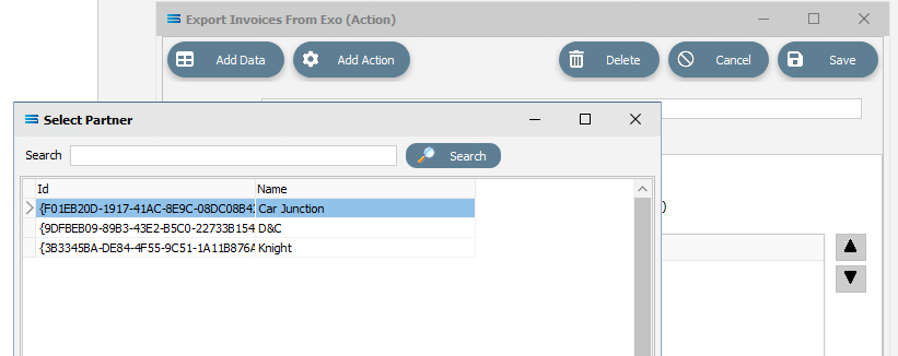
All 3 partners now need to be selected and added to the Action. To add a Trading Partner to the list for this Action, double-click on the customer that you want to include. This will add only one partner at a time and after every add you will return to the Export Invoices From Exo (Action) window. Start by double-clicking on Car Junction. The customer you have just added will appear within the Trading Partner pane.
To add more than one partner, you will need to select Add for each partner addition by repeating steps 5 and 6 as required.
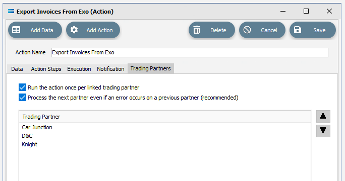
Once all three Trading Partners have been added, select Save to save and close the Action.
Specify Individual Output Folders
To direct the output invoices into their own unique partner-specific folder, now select Training: Invoice from the File Connection list.
Click once to open it. Change the File Directory field to include the <TPName> tag. The field will now be <DefaultDir>\Training\Tutorial4\<TPName>\Invoice\. Adding this tag inserts a folder name into the path and drop the files down one level. Tab to exist the field.
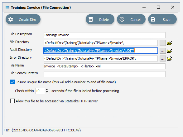
As soon as you tab out of the File Directory field, the Audit Directory and Error Directory fields will automatically be updated.
Now alter the File Name field to include a tag to write the Trading Partner name as part of the file name. When the File Connection was initially created, you entered Invoice_<DateStamp>_<FileNo>.xml as the File Name. Now you will need to change this to be able to write a file that includes an invoice number, customer ID, customer name, date stamp and file number in the File Name.
Change the contents of this field to:

The contents in the field will scroll to the left as you enter – to check your progress use the left and right arrow keys to move within the field. As a result of the Action, files should be produced that look like this example: Invoice_#10013_#4_Car Junction_20220507124034_2.xml
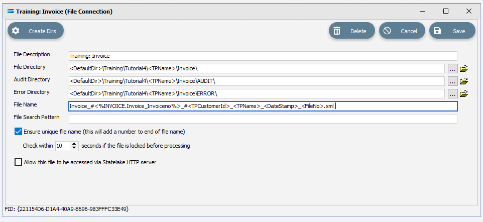
Tab out of the field, then select Save to save and close the File Connection window.
Run The Action
Now, back to the Action. Right-click on Export Invoices From Exo, and select Run Action.
The Action will quickly process, and once complete will present a confirmation pop-up.
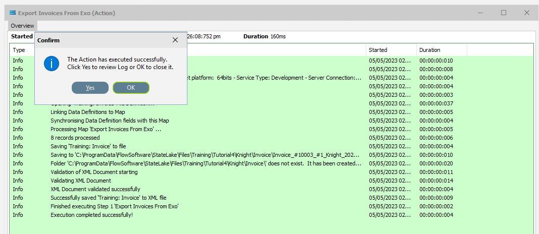
Select OK or Yes to proceed.
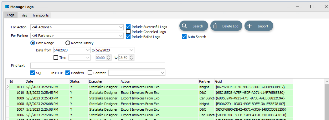
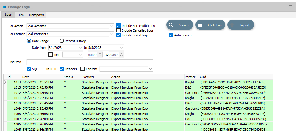
Once the on-screen preview log has closed, click on Logs at the very end of the structure tree. The Log listing will show that the Action successfully completed running three times – one for each of the Trading Partners.
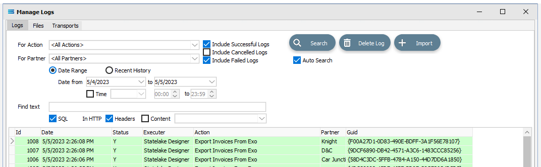
To see any cancelled logs, tick the box labelled Include Cancelled Logs. Successful logs will display with a GREEN background, failed with a PINK background, and cancelled logs with a pale YELLOW background.
Click on the X to close Manage Logs.
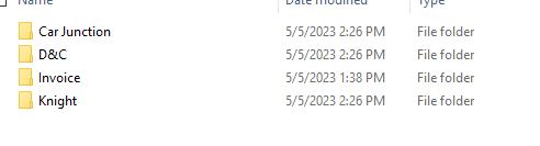
As a check on the success, navigate to the Tutorial4 folder as specified in the File Connection, and you will see that there are three additional sub-folders – one for each partner that was specifically created.
And the invoices are located each of these inside under another folder named Invoice.
Outbound Transports
Outbound Transports facilitate the transfer of files from the Statelake environment, to a remote environment or other system. A typical example that illustrates the use of Outbound Transports, is where EDI is used between Trading Partners.
As an example, where a supplier is sending electronic invoices to a company such as Mitre 10. Outbound Transports will only transport files, and not databases or tables.
The Outbound Transports functionality is demonstrated through the use of a LAN as the transport solution.
Outbound Transports can be found under the Transports umbrella on the structure tree on Designer.
Create The Transport
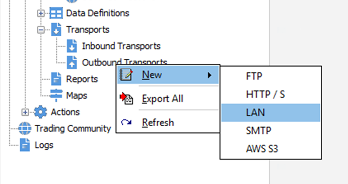
Follow the path Configuration > Components > Transports.
Double-click on Transports to expand it, then right‑click on Outbound Transports and choose New from the drop-down list. When presented with a further selection, click LAN.
A New LAN Transport item appears in the structure tree under Outbound Transports. In the New LAN Transport window, specify the following details:
Description - a meaningful explanation for this transport. Enter Knight Invoices
UNC Path - the sub-directory which will contain the files. For the purposes of this tutorial enter \ProgramData\FlowSoftware\Statelake\Temp.
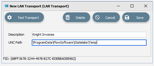
Select Save to save and close the New LAN Transport window.
Select The File Connection For Transport
Now click on Trading Community on the structure tree, and select Knight from the Trading Partners list, once it is highlighted, then click Edit.
.
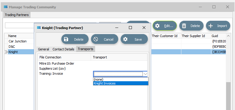
The Knight (Trading Partner) window will open on the General tab. Move to the Transports tab, and click on Training: Invoice in the File Connection list.
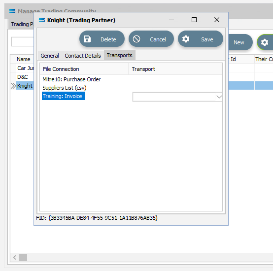
A list of available Transports will appear as a pull-down list. Click on the down arrow to reveal all of the choices. Select the newly created Knight Invoices, to activate the use of the LAN connection for this Trading Partner.
Select Save to save and close the Knight window.
Close the Manage Trading Community window by clicking the X.
Run The Action
Click on Actions or click on the plus sign to the left of Actions to expand the tree. Right-click on Export Invoices From Exo, and select Run Action.
The Action will quickly process, and once complete will present a confirmation pop-up. Select OK or Yes to proceed.
Once the on-screen preview log has closed, click on Logs at the very end of the structure tree. The Log listing will show that the Action successfully completed running three times – one for each of the Trading Partners. It looks no different from the previous run.
However, if you then double‑click on the log for Knight, you will see near the bottom of the log that the Action has successfully written to the LAN folder.
Click on the X to close the Log Detail, then on X again to close the Manage Logs window.
As a check on the success of the Outbound Transports to the sub-directory, navigate to the \ProgramData\FlowSoftware\Statelake\Temp folder, and you will see that an XML invoice file has been written for the customer Knight, just like the example below.

Marking Transactions As Extracted
No-one likes to be charged more than once for something, so it is important to know which invoice records have been extracted and invoiced, so that they are not extracted again in error and a duplicate invoice raised. Statelake handles this with ease, by using a field named X_FLOID. This is an ID field.
Marking Transactions
Designer will already be open. If not, open the Statelake module Designer for the selected configuration. An expanded structure tree is displayed on the left side of the screen.
Set The DB Definition Criteria
Click on the DB Definition called Exo: Invoices Out to open the definition window.
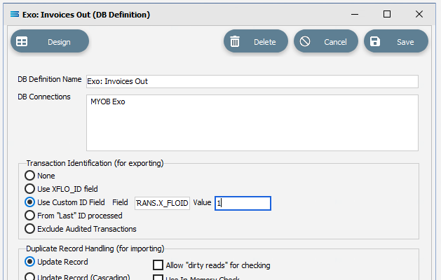
Under Transaction Identification (for exporting) section, click the Use Custom ID Field radio button, and enter the following details:
Field – an additional field used to reflect extraction status. Enter DR_TRANS.X_FLOID
Value – the value to identify the record as extracted. The field is to hold a value of 1 when the record has been fully processed. Enter 1.
When an invoice database record has NOT been processed, the value held in DR_TRANS.X_FLOID is set to minus 1 (-1). To indicate that an invoice has already been generated for the record (we do not want to duplicate the invoice), this DR_TRANS.X_FLOID value is therefore set to 1 one (1).
Click Design to open the designer canvas which will be populated with the three dataviews.
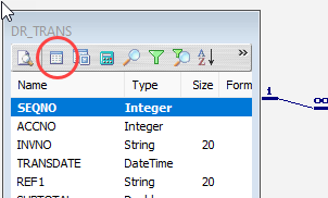
Open the Query Designer by clicking the Tables tab for the dataset DR_TRANS.
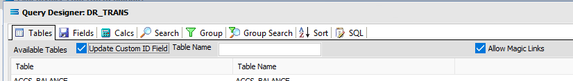
On the grey label bar, tick the checkbox to Update Custom ID Field.
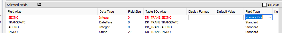
Move to the Fields tab and expand the lower pane as required, so that SEQNO is showing as one of the Selected Fields. Click on SEQNO to highlight the line, then change the Field Type from Standard to Primary Key using the pull-down box.
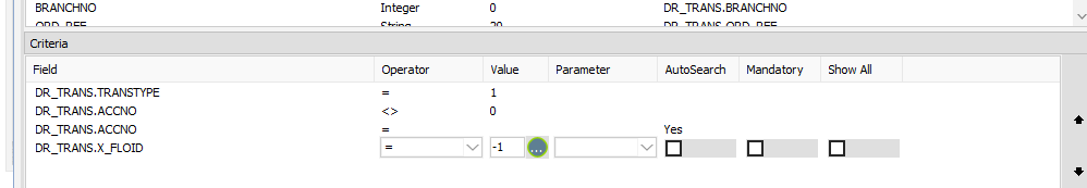
Then move to the Search tab and modify the search criteria for the field X_FLOID. This field has already been selected and should appear in the lower pane with the Show All set to Yes:
Click on the line in the lower pane, then click the Show All box to untick it.
Enter -1 into the Value column for that line.
This will ensure that once the record is processed, and the X_FLOID value is returned to a one (1), then the record will not be included in the query results again. So the record can only be extracted once.
Click OK to save and close the Query Designer.
Select File and Close to save the definition and close the designer canvas.
Save the definition using the Save button.
Run The Action
Return to the Actions branch on the structure tree, and right-click on Export Invoices From Exo, and select Run Action.
The Action will quickly process, and once complete select OK or Yes to proceed.
Once the on-screen preview log has closed, click on Logs at the very end of the structure tree. The Log listing will show that the Action successfully completed running three times – one for each of the Trading Partners.
However, now each record has been flagged as extracted, so no further extraction of these records will be possible. Remember that when a record has been processed and an invoice generated, the DR_TRANS.X_FLOID will be set to 1 - indicating the invoice has already been generated.
Close the window by clicking on X.
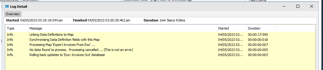
As a test of this, run the Action again, and you will see that there will be no further processing of these records. The yellow Log background shows that the Action was Cancelled to to finding no records to process - they have been been flagged as already generated.
Summary
Congratulations! A two-level XML has now been generated from a multi-tier database source query. And you have proven your skills as a Statelake Tag titan!
In summary these are things that have been achieved for this configuration in this tutorial:
XML File Definitions have been configured to writing to XML files to generate invoices.
Tags have been introduced. A full list of usable tags is available on the online Statelake help.
Trading Partners and the Trading Community have been used.
The use of Outbound Transports to achieve your goal.
How to flag records as extracted to avoid duplications using X_FLOID.
Quick Recap Quiz
Your adventures into the extensive functionality of Statelake continues. How good is your memory? These are some tricky questions.
Schema files (.xsd) are linked to what other type of file?
a. Flat file b. EDIFACT c. XML
2. Enabling users to enter their own criteria during a search operation employs which function?
a. AutoSearch b. Interactive Search c. Stab-in-the-dark
3. What is the Statelake module that specifies database names, and access credentials?
a. DB Definition b. DB Connection c. File Connection
4. Which Statelake module allows a file to be sent to a remote location?
a. Maps b. Outbound Transports c. Trading Community
5. The variable that is used to substitute dynamic values in a screen form?
a. Interloper b. Earmark c. Tag
6. What is the name of the highest node in a tree structure?
a. Root node b. Leaf Node c. Fat Branch
7. The Statelake Map defines how the output is to be created. What can a Map not do?
a. Change the output structure b. Calculations c. Output records
8. Which items can be used to represent external entities such as customers?
a. DB Connections b. Trading Partners c. Outbound Transports
9. After being first written, how many times can a Log file be re-opened and reviewed?
a. As many times as required b. None c. Only once
10. Can Statelake produce multiple output files in one run?
a. Yes, but with difficulty b. No c. Yes, easily
11. Script variables are used to powerful effect in which Statelake module?
a. Action b. Map c, Transports
12. A symbol that is used in formulae, expressions, or calculations, is called what?
a. Operator b. Server c. Key
13, What Statelake program allows you to define a configuration database service?
a. Designer b. Manager c. Monitor
What is the correct TRANSTYPE for an invoice?
a. 1 b. 2 c. 3
Next Steps
This tutorial is the final in the initial series, and bring together all of the things you have learnt so far, while introducing some new and exciting functions.
You are fast becoming familiar with the incredible versatility and power that is Statelake.
The following additional tutorials build on the knowledge foundation so far, and introduce some more exciting features.
Tutorial 5 - Statelake Magic SQL
Tutorial 6 - Import CSV Purchase Orders Into A Database
Tutorial 7 - Exporting And Importing Configuration Data
Tutorial 7 - Exporting And Importing Configuration Data
Quick recap quiz answers
c 2. a 3. b 4. b 5. c 6. a 7. a 8. b 9. a 10. c 11. b 12. a 13. b 14. a