Tutorial 6: Import CSV Purchase Orders Into A Database
For the purpose of this tutorial we are generating the identical destination output as Tutorial 3, and using the same data values, but in a different file format and structure.
When the data structures are the same on the source and destination sides of the map, then the process of linking them is straight forward by dragging each portion of the source onto its counterpart in the destination, to create the LinkedData relationships.
For example, order header on the source links to order header on the destination, and order lines on the source links to order lines on the destination.
Sometimes however, the source and destination structures do not match and we need to adjust the map to accommodate the differences.
In this case, the header and lines data is squashed into one level in the source, but we still want a 2-level structure for the destination.
The database will be the same Exo database that we have already worked with in previous tutorials, MYOB Exo.
This tutorial represents a case of a supplier receiving electronic purchase orders and automatically processing them into Exo, along with some order validation.
We will be using the Statelake configuration called Statelake_Training for this tutorial.
It is most important before you proceed, to check and ensure that all of the training files have been copied as instructed. These files are an essential part of this tutorial.
Where The Data Is - Database Connections
In this tutorial, an Exo database will be used as the destination, so the DB Connection to the Exo database MYOB Exo that has already been established in earlier tutorials can be used, as the information is the same. We do not need to re-create or duplicate it. However, if the previous tutorials have not been completed and the DB Connection to MYOB Exo has not been established, then follow the directions below to generate this DB Connection.
If MYOB Exo Already Exists
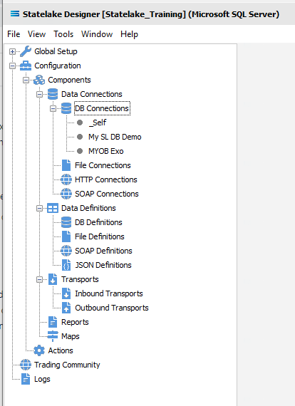
The first step is to make sure that Statelake module Designer for your selected configuration Statelake_Training is open. An expanded structure tree will be displayed on the left side of the screen.
Follow the path Configuration > Components > Data Connections > DB Connections. Click on DB Connections and MYOB Exo should be displayed.
If MYOB Exo Does Not Already Exist - Create DB Connection
Follow the path Configuration > Components > Data Connections > DB Connections. Click on DB Connections and once DB Connections is expanded, you will see a connection called _Self. Right‑click on DB Connections and choose New from the drop-down list.
New DB Connection appears as an entry under DB Connections. In the New DB Connection window the following information is to be entered.
Connection Name – some source databases will have obscure or convoluted names. This field is the user-friendly identifier name that will appear in the Statelake configuration and references the source database. Enter MYOB Exo. The two tick boxes Use Config Database and Use Config Database Server Only should be left blank.
The lower screen is then split into two tabs - General and Advanced. The Advanced tab allows you to set other options, but for training purposes, we will be dealing with just the General tab.
Connection Type – select the database engine that is to be used. Since the configuration Statelake_Training has been up using Microsoft SQL Server, ensure that the radio button Microsoft SQL Server is selected.
Server Name – the server location for the source database. Enter the server name – the name that was used to log on to either Microsoft SQL Server Management Studio.
Database Name – the name of the database. Enter Data_Demo.
User Name and Password – fill these out with SQL authentication details or leave them blank to use Windows Authentication.
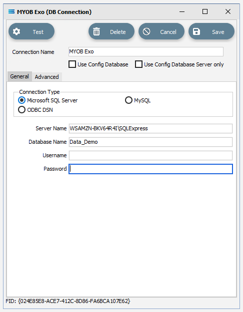
Click on the Test button in the top left of the window when all details are populated. If the details are all correct, you will be presented with a message “Connection Test Successful”. Click Ok to proceed. If the test is unsuccessful, you will see the error reported by the database server. Correct any errors as required.
It is impossible to cover all possible errors that may come from a database connection because any errors are specific to the type of the database involved, and each database type may have hundreds of errors than could be generated. If you do not know what the error is, then try searching the web for documentation about errors for the type of database you are attempting to connect to.
If the connection test is successful, click Save to save and close the connection module.
Along with an automatically generated DB Connection named _Self, the DB Connection named MYOB Exo will now appear in the structure tree under Configuration > Components > Data Connections > DB Connections.
Where The Data Is - File Connections
As we know, the File Connections module also sits under the Data Connections umbrella, and is the configuration module that points to a specified file directory that can hold either or both the source file or destination file. In this tutorial, the output file will be an Exo database, and the source will be a CSV file. So a new file connection for the input/source file needs to be created.
Designer will already be open. If not, open the Statelake module Designer for your selected configuration. An expanded structure tree is displayed on the left side of the screen.
Create File Connection
Follow the path Configuration > Components > Data Connections > File Connections. Right‑click on File Connections and choose New from the drop-down list.
A new item called New File Connection will appear in the structure tree. In the New File Connection window the following information is to be entered.
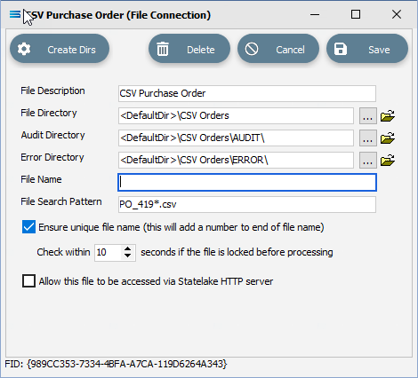
File Description – the name that is meaningful and best describes the file. In this tutorial the description given this connection will be CSV Purchase Order.
File Directory – the directory location of the file. Enter <DefaultDir>\CSV Orders. Use tab to exit the field and move on.
The <DefaultDir> tag refers to the default file path already set up within the Statelake General Setup, under Global Setup. By default, C:\ProgramData\FlowSoftware\Statelake\Files will be the file directory referenced by this tag.
c. Audit Directory – will be automatically populated when you tab out of File Directory.
d. Error Directory – will be automatically populated when you tab out of File Directory.
Statelake uses two sub-directories to manage files - AUDIT and ERROR. When a file is successfully processed in, or successfully sent after being written out, it is moved into the AUDIT directory. If an error occurs during file processing, the file is moved into the ERROR directory.
e. File Name – the actual name of the file. In this tutorial, leave this field blank as this connection will not be used to produce any new files – we just want to read from the file.
f. File Search Pattern - used by Statelake when files are being read. Enter PO_419*.csv to locate all files that match this search criteria. This should locate the two sample CSV files called PO_41919.csv , and PO_41920.csv that are to be used for the source. The asterisk * is a wildcard and replaces any letter in the search. Each of these CSV files contain data pertinent to orders.
g. Ensure Unique File Name – tick this box to add a number to the file name to ensure that the file name will be unique and will not overwrite a file already in the output folder.
h. Allow This File To Be Accessed – for this tutorial leave unticked.
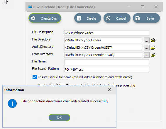
If the sub-directories you have specified do not yet exist or you are not sure whether they exist, you will need to check by clicking on the button Create Dirs which is located on the top left of the window.
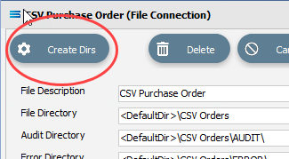
If they do not exist, they will be created, else they will be confirmed as current and available by display of the pop-up message “File connection directories checked/created successfully”. Click OK in response to the successful creation message.
Click Save when all details are entered to save and close the module.
The File Connection named CSV Purchase Order will now appear in the structure tree under Configuration > Components > Data Connections > File Connections.
What The Data Is - Creating File Definitions
The File Definitions module is used to design the structure of the files that are either read from, or written to the Statelake configuration. There are four types of files that can be specified in this module - “flat” text files, XML files, Excel (binary), and EDI (EDIFACT) type files.
This tutorial uses a .CSV file purchase order file as the source, so this definition configures the source file.
Designer will already be open. If not, open the Statelake module Designer for the selected configuration. An expanded structure tree is displayed on the left side of the screen.
Create File Definition
Follow the path Configuration > Components > Data Definitions > File Definitions. Right‑click on File Definitions and choose New from the drop-down list.
New File Definition appears as an entry under File Definitions. In the New File Definition window under the General tab, the following information is to be entered.
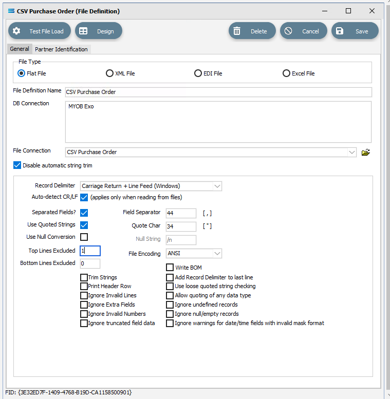
File Type – leave the selection as Flat File.
File Definition Name – enter the definition name of the destination file, as specified during the creation of the File Connection. In this tutorial it is CSV Purchase Order.
DB Connection – right-click anywhere in the empty DB Connection box to see the Add pop-up, and a list of all the found connections will be displayed. Select the one you want from the list – as with the DB Definition, _Self will display, along with MYOB Exo. A source database is required to be selected for all definitions - select MYOB Exo.
File Connection - select CSV Purchase Order from the pull-down list.
Disable Automatic String trim – this is ticked. Leave with the default tick as set.
Record Delimiter – leave as set, as Carriage Return + Line Feed (Windows).
Auto-detect CR/LF – this applies only when files are being read, so make sure that this box is ticked.
Separated Fields? – tick the box to separate the fields, and the Field Separator field will populate as 44 and comma [ , ]. Leave as ticked.
Use Quoted Strings – tick the box to activate, and the Quote Char field will populate as 34 and quote [ “ ]. Leave as ticked.
Top Lines Excluded - the first row in the CSV file is column/field names, so we want to ignore the top row. Enter 1 into this field.
All other fields and tick boxes are to be left as set.
Click Design in the top of the window.
Create File Dataview Query
A blank definition designer canvas will display. To start creating your file, click on the File menu in the top left corner, and choose New (or use the Ctrl+N).
The New Items window will open and only two items called File Dataview and DB Dataview will be displayed. File Dataview should be selected - if not, select File Dataview and click OK to add a new File Dataview. The File Designer window will open.
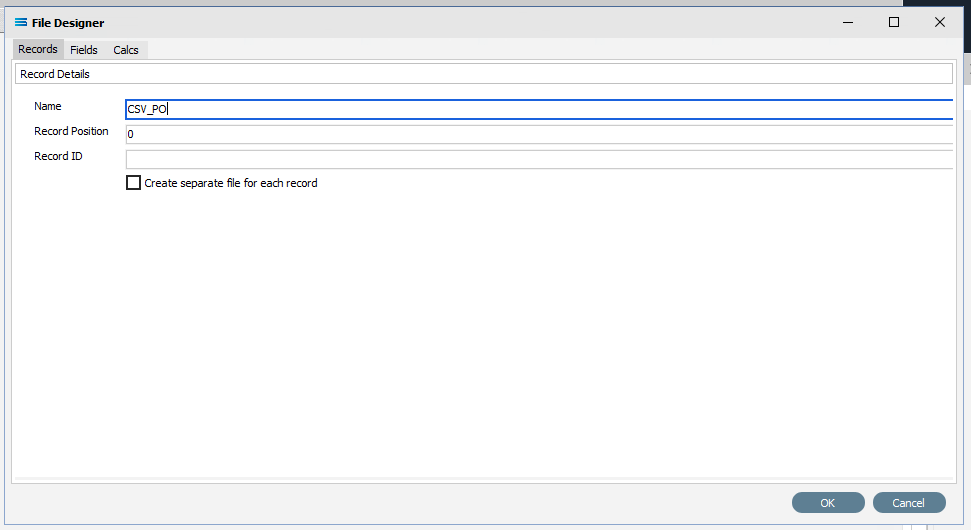
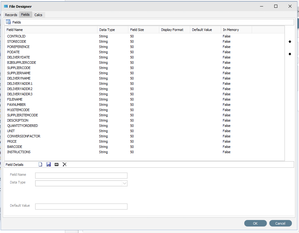
Unlike Query Designer, all records and fields in File Designer are entered manually when creating a flat text file. The first tab of 3 is Records, and the section Record Details.
Name – an alphanumeric field, this is the name given to this dataset. It will be referred to throughout the Statelake configuration for mapping purposes. This name will also prefix the column names when printed. In this tutorial the record Name is CSV_PO.
Statelake forces all records and field names to be entered as uppercase for consistency across all definitions.
b. Record Position – this is a numeric integer value that is used to manage the sequencing of records at the same level within the file. For this tutorial use 0 (zero). This only applies for output.
c. Record ID – an alphanumeric field that accepts both upper and lower case. Record ID is to be left blank for this tutorial.
d. Create separate file for each record – we want only one supplier record file so leave this box unticked.
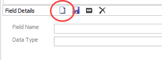
The next tab is Fields. The window is split into two panes. The upper pane Fields shows the fields as they are created, while the fields themselves are created in the lower pane Field Details. In the lower pane. click the Add Field icon (1st icon, blank page) to create a field.
Tab to move between fields. These steps are to be repeated for all the fields listed below.
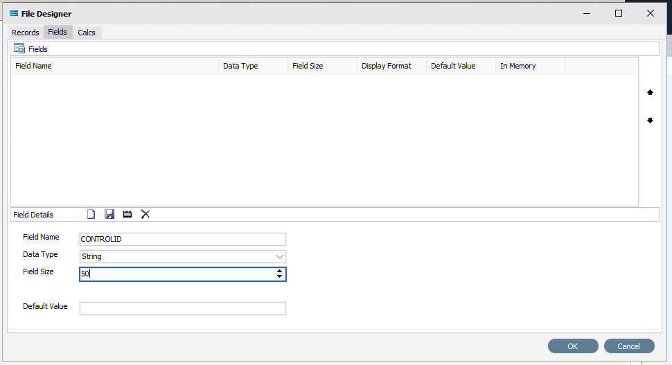
a. Field Name – a meaningful name to describe the contents of this field. The first field name is CONTROLID. Input is forced to uppercase.
Be consistent with your naming conventions. Decide on the use of a separator such as a hyphen ( - ) or an underscore ( _ ) to split multiple word record or field names, and it is best to try not to deviate from whichever convention you decide to use.
b. Data Type – from the pull-down list select the record type. CONTROLID will be an String , although other types including boolean and integer are able to be selected as required.
c. Field Size – the number of characters in the string. Set this value to 50.
d. Default Value – a default value for the field, such as populating the field with M for a tax code field. Unless otherwise specified, leave blank.
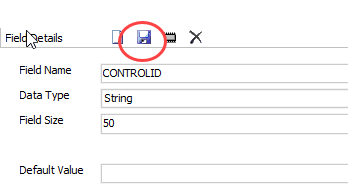
Click the Save icon (floppy disk) to save the field. The field and details appears in the upper pane.
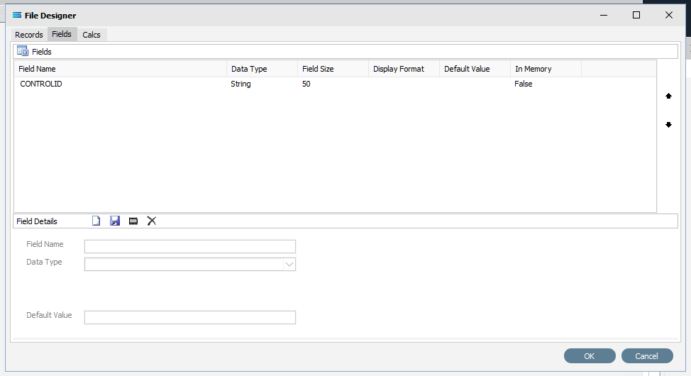
If you accidentally click OK rather than Save and return to the File Designer screen, simply tab across to the Fields tab (3td tab), and continue where you left off.
Repeat creating fields as per 4 and 5 above to create all the additional required fields. You could enter every field one by one - all set at string 50. There are 22 fields. So a slightly easier and quicker method is to copy the field CONTROLID that we have already created. To copy the field, right-click on the CONTROLID field name in the upper pane, and click on Copy.
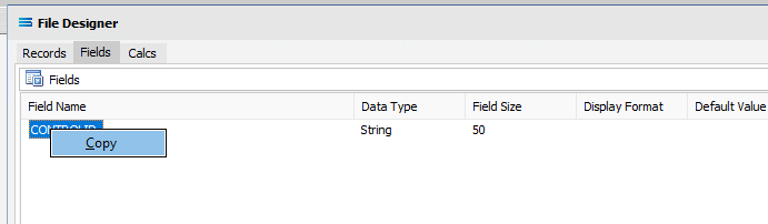
This duplicates the field in the upper pane.
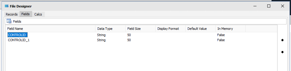
Simply change the field name - the 2nd field is STORECODE. Click on the name CONTROLID_1 and change the name when it populates the fields in the lower pane. Click on the Save icon or the next field down the list in the top pane to implement the change.
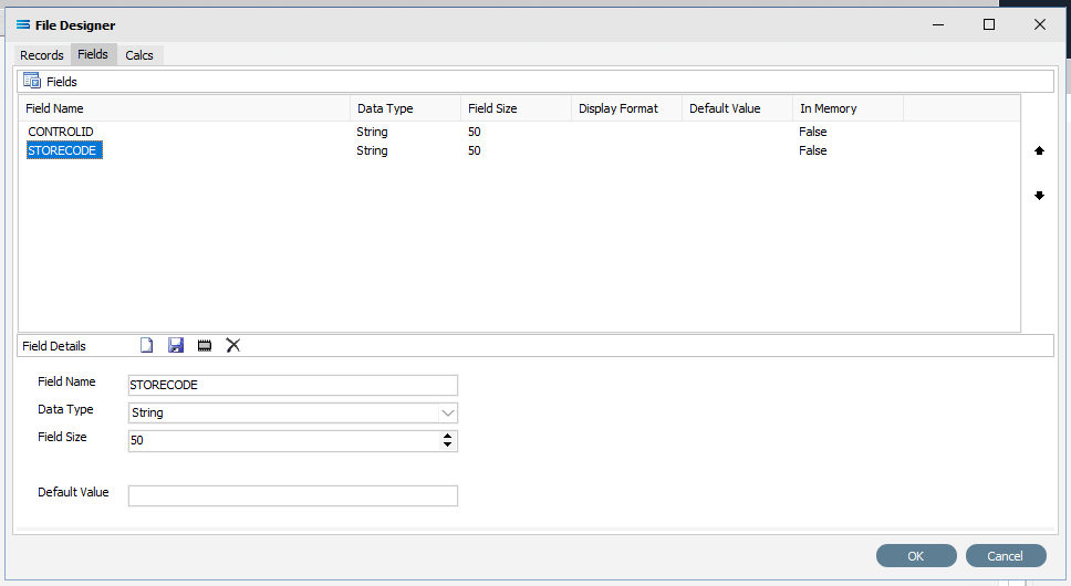
You can either duplicate the field another 20 times and then change each line in turn, or copy and re-name line by line. If you make a mistake and wish to delete a field from the upper pane, simply double-click it.
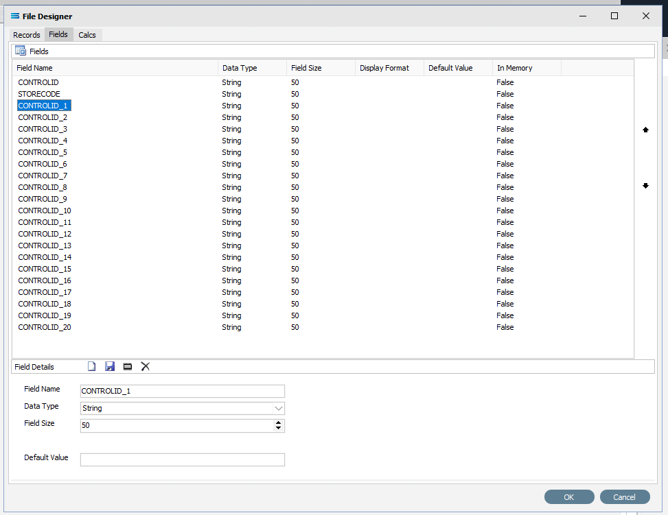
The other fields to be created are as listed below -
POREFERENCE
PODATE
DELIVERYDATE
B2BSUPPLIERCODE
SUPPLIERCODE
SUPPLIERNAME
DELIVERYNAME
DELIVERYADDR1
DELIVERYADDR2
DELIVERYADDR3
FILENAME
FAXNUMBER
M10ITEMCODE
SUPPLIERITEMCODE
DESCRIPTION
QUANTITYORDERED
UNIT
CONVERSIONFACTOR
PRICE
BARCODE
INSTRUCTIONS
Click OK when you are finished adding all of the fields, to save and close the File Dataview.
On return to the canvas, the CSV_PO record will display under New File Definition. Expand the CSV_PO window as desired.
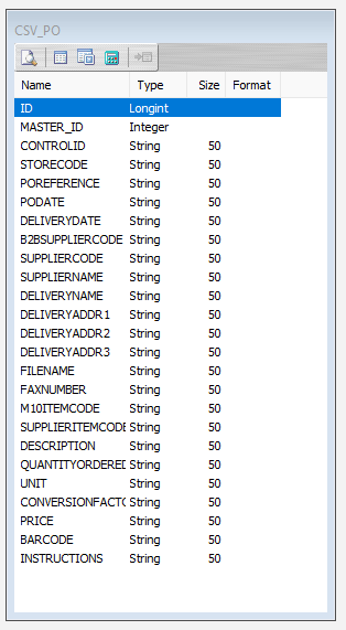
Close the definition canvas once you are satisfied that you have identified all of the source fields, by selecting selecting Close from the File menu. You will return to the New File Definition window. Click Save to save and close the module.
The File Definition named CSV Purchase Order will now appear in the structure tree under Configuration > Components > Data Definitions > File Definitions.
All required connections and definitions for this tutorial have now been configured. The mapping process is next.
What The Data Is - Creating DB Definitions
The DB Definition tells Statelake what the data is, so that the proper fields can be accessed and the data extracted correctly, which means defining the exact information to be extracted. The DB Definition also identifies how the output file is to be constructed.
Sitting under the Data Definitions umbrella, Statelake uses the DB Definitions module to define these data structure components, and to design the database queries for both reading the data out of, and writing in to, the databases. Illustrating the subtle but important differences with this type of destination definition, this tutorial uses two related tables for the output, or destination.
Designer will already be open. If not, open the Statelake module Designer for the selected configuration. An expanded structure tree is displayed on the left side of the screen.
In this tutorial, the DB Definition that has already been established in earlier tutorials called Exo: Sales Orders In can be used, as the information is the same. We do not need to re-create or duplicate it. However, if the previous tutorials have not been completed and the DB Definition called Exo: Sales Orders In has not been established, then follow the directions below to configure it.
If Exo: Sales Orders In Already Exists
The first step is to make sure that Statelake module Designer for your selected configuration Statelake_Training is open. An expanded structure tree will be displayed on the left side of the screen.
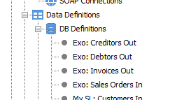
Follow the path Configuration > Components > Data Definitions > DB Definitions. Click on DB Definitions and Exo: Sales Orders In should be displayed.
If If Exo: Sales Orders In Does Not Already Exist - Create DB Definition
Follow the path Configuration > Components > Data Definitions > DB Definitions. Right‑click on DB Definitions and choose New from the drop-down list.
The item New DB Definition will appear in the tree. In the New DB Definition window the following information is to be entered.
DB Definition Name – the name that is meaningful and best describes the query/extraction. We will use Exo: Sales Orders In.
DB Connections – this is the name of the source database, identified by the meaningful name that was given in the DB Connections module. Right-click anywhere in the box to see the Add pop-up, and a list of all the found connections will be displayed. Follow the arrow and select the one you want from the list – in this tutorial, it will be MYOB Exo.
Remember, that if you select the incorrect DB Connection, simply double-click on the name of the DB Connection within the box to de-select it, and start again. It is very easy to correct.
c. Transaction Identification – leave with the defaults as set.
d. Duplicate Record Handling – leave with the defaults as set.
e. Disable Automatic String Trim – leave with the default as set. This box is ticked.
f. Save Null Fields as Blank Strings – leave with the default as set.
g. Disable SQL Transactions – leave with the default as set.
h. Save Blank String Fields as Nulls – leave with the default as set.
i. Include Null Values in SQL statement – leave with the default as set.
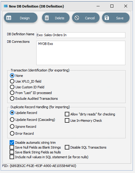
Click Design in the top left of the window.
Create 1st DB Dataview Query
A blank definition designer canvas will display. To start creating your query, click on the File menu in the top left corner, and choose New (or use the Ctrl+N).
The New Items window will open and only one item called DB Dataview will be displayed. Click OK to add DB Dataview.
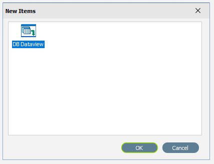
The Query Designer window will open.
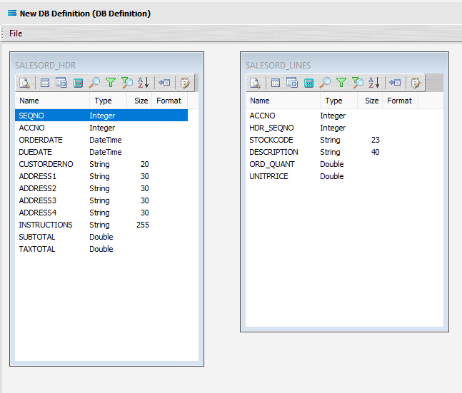
The first tab in the Query Designer is Tables. The upper pane contains a list of available tables in alphabetic order, and the lower pane will display the tables that you have selected during this process. Scroll down the available tables to SALESORD_HDR (Sales Order Header) and double-click to select it. It will appear in the lower pane as a selected table, while still remaining visible in the upper pane.
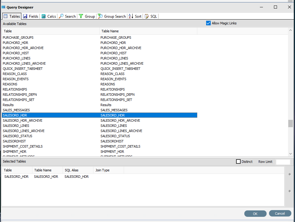
You may have to expand the window height to see a greater number of entries.
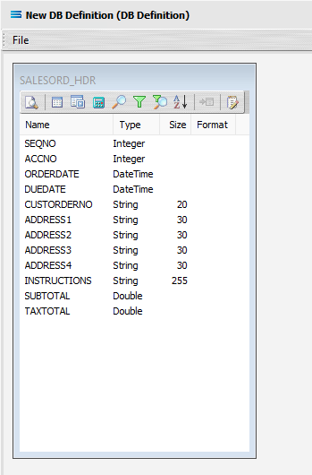
Move to the Fields tab, and add the following fields to query by double-clicking on them. As each one is selected, it will disappear from the upper pane and appear in the lower pane. SEQNO will be displayed in RED.
If you make a mistake and select the wrong field, then simply double-click on it in the lower pane and it will de-select and reappear in the upper pane.
SEQNO (sequence number)
ACCNO
ORDERDATE
DUEDATE
CUSTORDERNO
ADDRESS1
ADDRESS2
ADDRESS3
ADDRESS4
INSTRUCTIONS
SUBTOTAL
TAXTOTAL
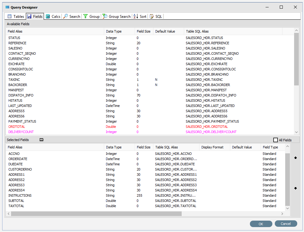
The fields are colour coded in the Query Designer. RED indicates that the field is either calculated or is an automatically generated IDENTITY type such as SEQNO. PINK indicates that the field does not allow null values.
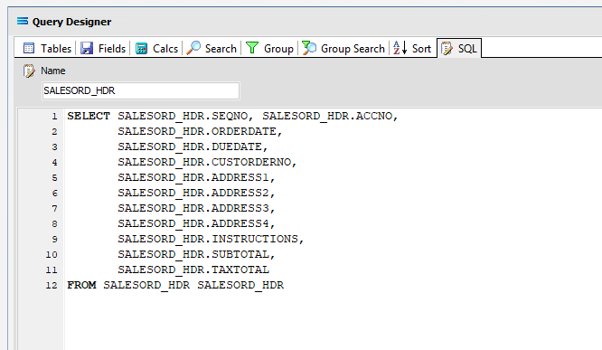
Click on the SQL tab to see the SQL query that has been generated. It lists the fields you selected and the table they are to be retrieved from. You will see that each field is prefixed with the table name with a full-stop as a separator.
Click OK at the bottom-right of the Query Designer to save the dataview and return to the definition canvas. The configured dataview will display, listing all of the selected fields. Expand this window as required.
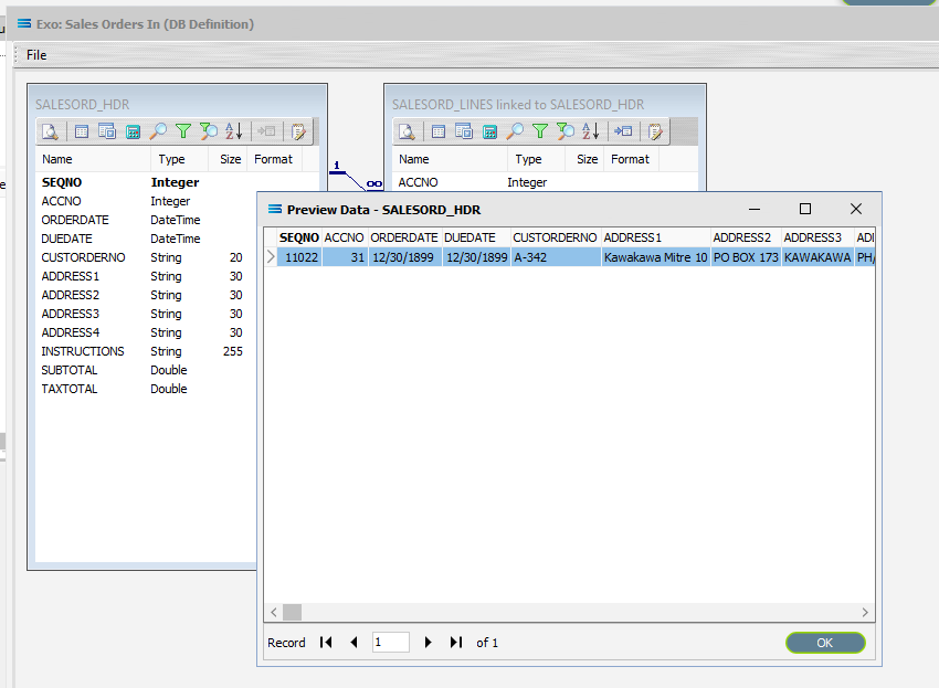
Click on the Preview button to run the query and see the results which will open in a specific window called Preview Data – SALESORD_HDR.
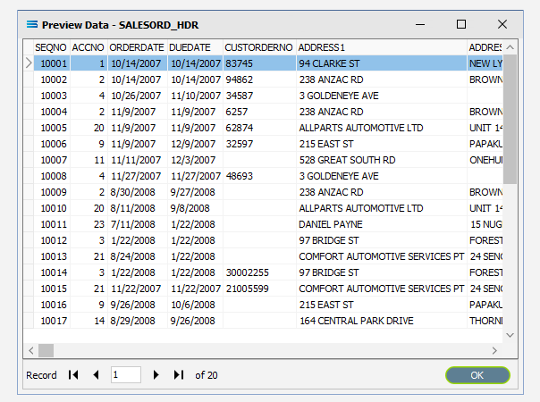
Click OK at the bottom of the preview window to return to the definition canvas and the open dataview.
Create 2nd DB Dataview Query
Create another DB Dataview by clicking on the File menu in the top left corner, and choose New (or use the Ctrl+N).
The New Items window will open and only one item called DB Dataview will be displayed. Click OK to add DB Dataview.
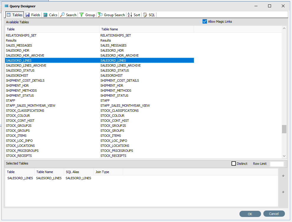
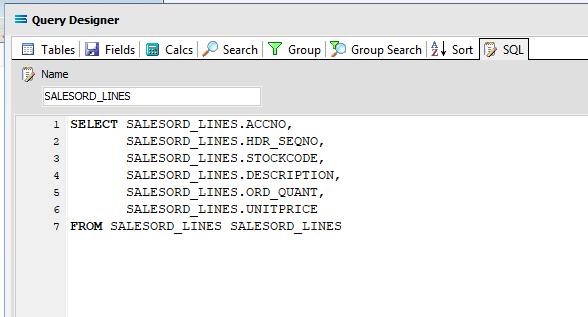
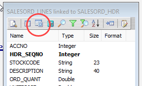
13. The Query Designer window will open on the Tables tab. The upper pane contains a list of available tables in alphabetic order, and the lower pane will display selected tables. Scroll down the available tables to SALESORD_LINES (Sales Order Lines) and just as we did for the SALESORD_HDR table, double-click on the SALESORD_LINES table to select it, and it will appear in the lower pane as a selected table.
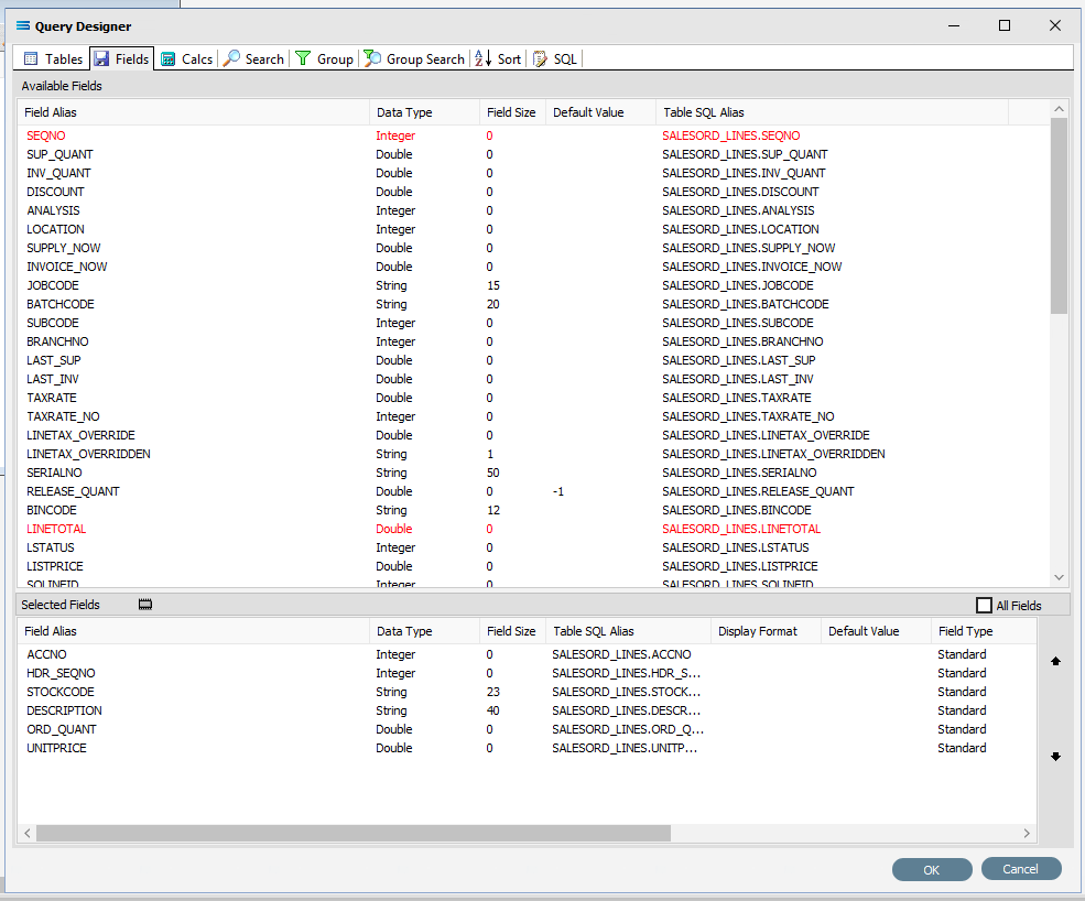
Move to the Fields tab, and add the following fields to query by double-clicking on them:
ACCNO
HDR_SEQNO (order header sequence number)
STOCKCODE
DESCRIPTION
ORD_QUANT
UNITPRICE
As you select fields from the Available Fields pane, they will appear in the Selected Fields pane, and disappear from the Available Fields pane.
You can click on the SQL tab to see the SQL query that has been generated. It lists all of the fields you selected and the table they are to be retrieved from.
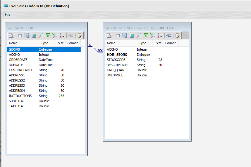
Click OK at the bottom-right of the Query Designer to save the dataview and return to the definition canvas. The configured dataview will display, listing all of the selected fields, so now there will be two definitions visible on the canvas - one named SALESORD_HDR and one named SALESORD_LINES. Expand the windows as required.
Link The Datasets
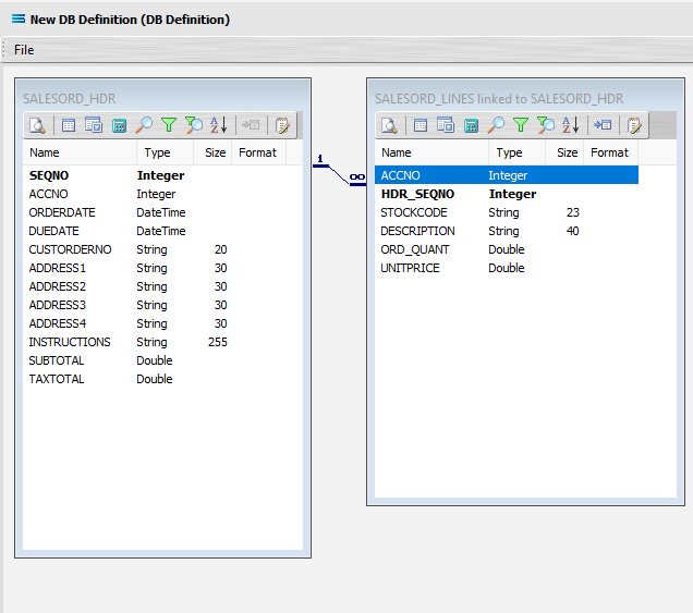
We want to link these together, so add a relationship between the two datasets by dragging the HDR_SEQNO field from the SALESORD_LINES dataview and dropping it onto the SEQNO field of the dataview SALESORD_HDR. Click on SALESORD_LINES.HDR_SEQNO and drag it over to SALESORD_HDR.SEQNO - once you see the drag label as below, then unclick to drop it.

Three things will happen. SALESORD_HDR will be renamed to SALESORD_LINES linked to SALESORD_HDR. A one-to-many relationship link will appear between the two dataviews - the “single” link pointing at SEQNO in SALESORD_HDR, and the many pointing at HDR_SEQNO in the renamed dataview SALESORD_LINES linked to SALESORD_HDR. These two linked fields will also be bolded.
Now we want to add some criteria. Either, click the Search tab on the SALESORD_HDR dataview to open the Query Designer window on the Search tab, or get to the same place by simply clicking on the Tables tab for the dataview, and when the Query Designer window opens, move to the Search tab. Expand the window as required.
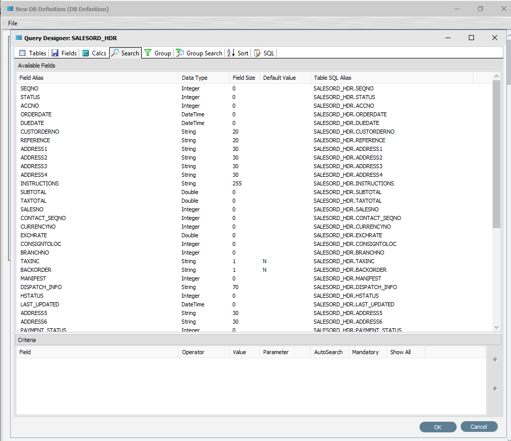
The upper pane shows the Available Fields, under the heading of Field Alias. Double-click on SEQNO in this list (SALESORD_HDR), and the field name will appear in Criteria pane. The field name will not disappear from the top pane once selected. To remove a field selected in error, simply double‑click on it in the Criteria pane to de-select.
To change the sort sequence of the field name list, click on the column name to toggle the sequence. Click once to sort in ascending alphabetic order from A - Z; click again to toggle in descending alphabetic order from Z - A; click again to return to the default sort sequence as per the table design.
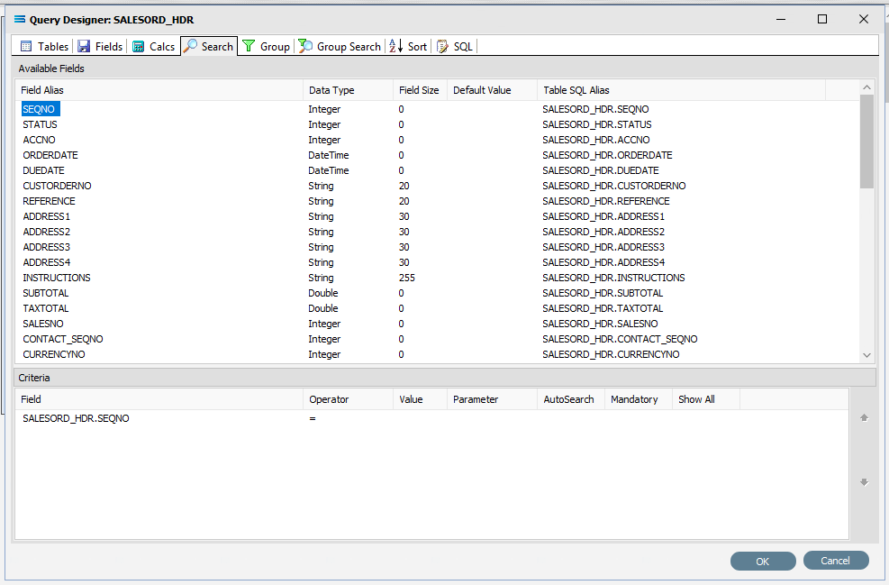
To the right of the field name in the Criteria pane, several extra fields will appear, including Operator and Value. Leave the Operator as defaulted as an equal sign (=), and enter -1 as the Value, to ensure that the DB Definition is empty when it is loaded into the map. If this dataset holds any data, then Statelake will produce an error, so to successfully insert or update data into a populated table, the search criteria is set to a value that will not exist in the table (such as -1), Tab out of the Value field.
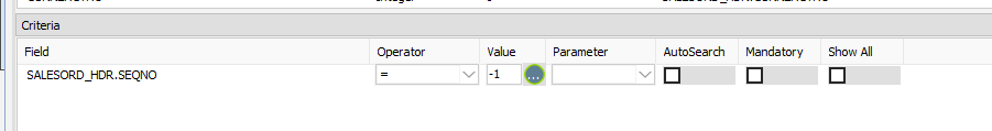
Statelake will generate an error during the start of mapping if the destination dataset contains any data prior to the operation. So by entering a value of minus 1 ( -1 ) into the value field, forces the destination dataset to be completely empty of any residual data.
Now leave the Search tab and move left into the Fields tab. Under Selected Fields, under the Field Type column, all the fields that you selected earlier will be displayed and all will have a Field Type of Standard. SEQNO will be displayed in RED.
Change the Field Type on SEQNO to Primary Key – Auto, by clicking on the Field Type for the line and selecting this option from the pull-down list. If Primary Key – Auto does not display properly, then expand the width of the column. Primary Key - Auto should be first at the top of the list.
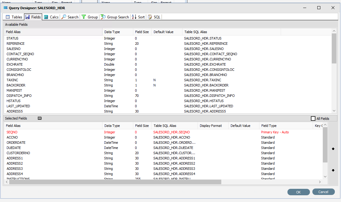
Selecting Primary Key - Auto identifies this field SEQNO as a field that will have its values automatically generated in the SALESORD_HDR dataset by the database server. This means that when a header record is written to SALESORD_HDR, a value will automatically be assigned to the SEQNO column/field. This SEQNO value is then written to the related line records into the HDR_SEQNO field in the SALESORD_LINES dataset, keeping the link between the two datasets accurate and well defined.
Click on the empty Key Generation column for this field to see the pull-down list of available values. If the column does not seem to populate, make sure that you have selected SEQNO and that the column fields are bordered. Select SELECT SCOPE_IDENTITY(). This option should be at the top of the list.
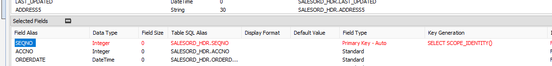
Using this as the Key Generation means that the system will keep a track of the last identity value that was accessed by this particular session query. This keeps the child records correctly linked to the appropriate parent record.
If the column width default for Field Type and Key Generation are too small to see the options in their entirety, expand the column widths as required by dragging with the mouse.
Click OK at the bottom-right of the Query Designer to save the dataview and return to the definition canvas.
Now, either click the Tables tab on the SALESORD_LINES linked to SALESORD_HDR dataview, and in the Query Designer window click on the Fields tab. Or, click on the Fields tab on the same table.
In the Selected Fields pane, set the Field Type on the HDR_SEQNO field to Foreign Key. The HDR_SEQNO Field Type is set to Foreign Key because the field is related to SEQNO from the SALESORD_HDR dataset, and with this setting Statelake will automatically assign the SALESORD_HDR SEQNO value to this field.

Click OK at the bottom-right of the Query Designer to save the dataview and return to the definition canvas.
Close the definition canvas by selecting Close from the File menu. You will return to the EXO: Sales Orders In window.
Click Save to save and close the module.
The DB Definition named EXO: Sales Orders In will now appear in the structure tree under Configuration > Components > Data Definitions > DB Definitions.
What To Do With The Data - Creating Maps
There have now been two definitions created for this tutorial – the File Definition called CSV Purchase Order, and the DB Definition called Exo: Sales Orders In.
Designer will already be open. If not, open the Statelake module Designer for the selected configuration. An expanded structure tree is displayed on the left side of the screen.
Create The Map
Follow the path Configuration > Components > Maps. Right‑click on Maps and choose New from the drop‑down list.
New Map will appear as an item on the tree. The New Map window contains two tabs - General and Parameters. The Parameters tab allows you to set other options, but for training purposes, we will be dealing with just the General tab. The following information is to be entered for the main map.
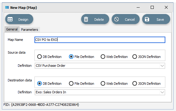
Map Name - this is the meaningful name that will identify the extraction process, and in this tutorial will be called CSV PO to Exo.
Source Data – highlight the File Definition radio button.
Definition – the File Definition that was created for this configuration called CSV Purchase Order can be selected from the pull-down list.
Destination Data – highlight the DB Definition radio button.
Definition – the name of the DB Definition that was created for this configuration called EXO: Sales Orders In can be selected from the pull-down list.
Open The Map
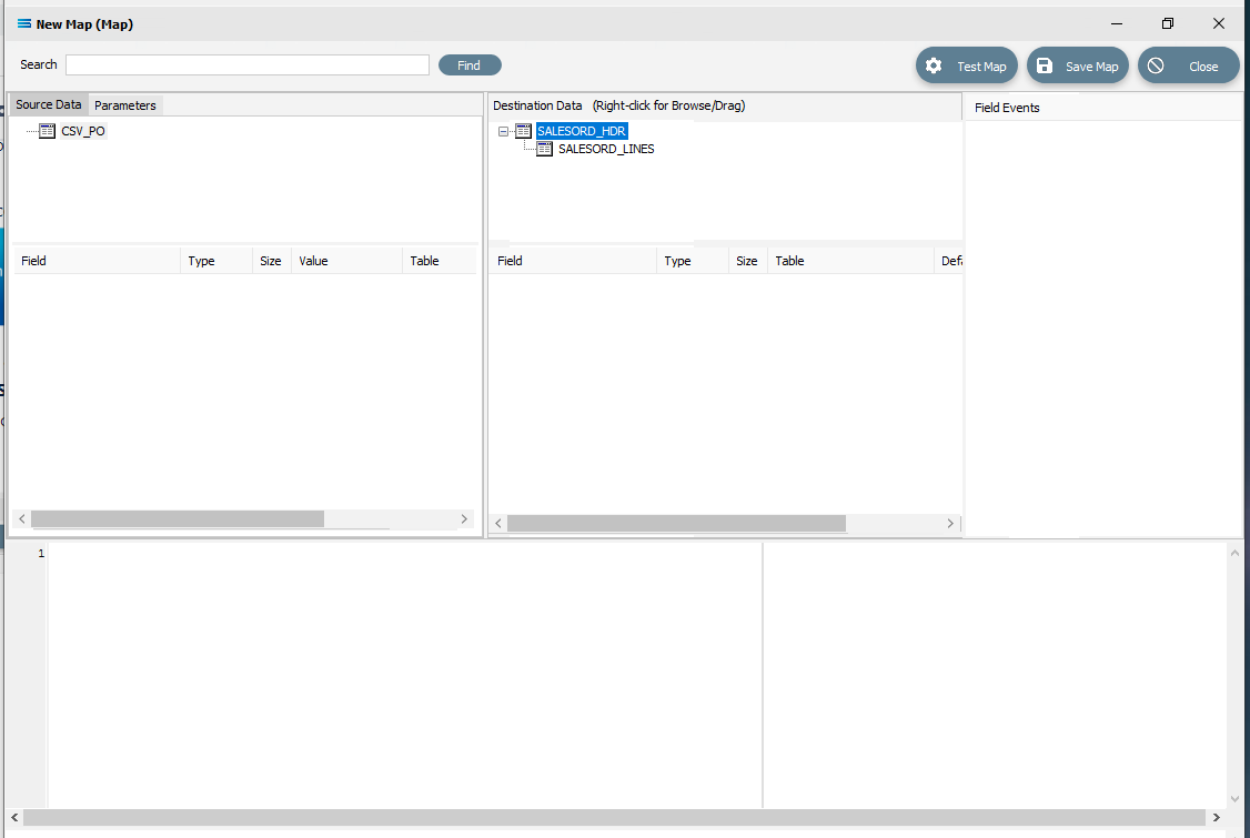
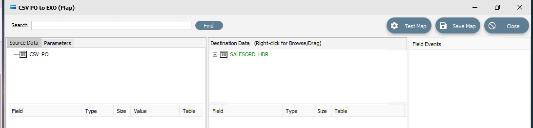
Click the Design button in the top left of the window to open the map designer window New Map.
The New Map screen is split into five distinct panes beneath the search bar.
Source is split into two panes with Source Data and Parameters tabs. This is the definition of the source that data is to be read from.
Destination Data is also split into two panes. This is the definition that the data is to be written to.
Field Events on the right side of the screen. The events of the selected dataset or record.
Scripting Area beneath the Source and Destination Data panes. Where the script of each event is displayed and edited.
Compiler Messages below the Scripting Area. Messages that are returned by the compiler.
The first mapping operation is the linking of the datasets, to ensure that for every record in the source dataset, there is a corresponding record in the destination dataset.
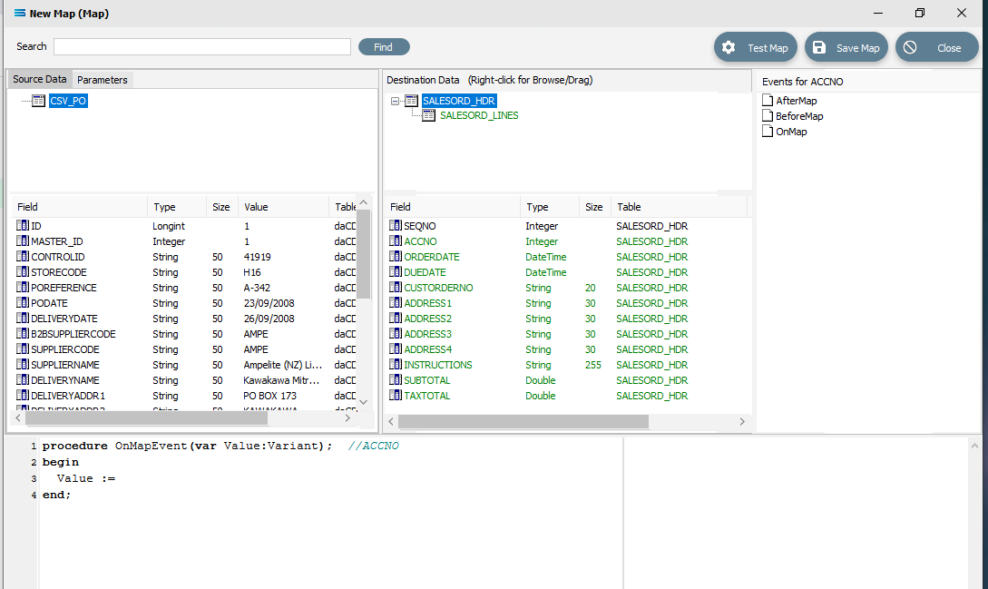
In this tutorial we will link the source data table CSV_PO to the destination SALESORD_HDR and SALESORD_LINES datasets. CSV_PO is already showing in the Source Data pane, and SALESORD_HDR is already showing in the Destination Data pane. If SALESORD_LINES is not displayed, click on the plus symbol beside SALESORD_HDR in the destination pane.
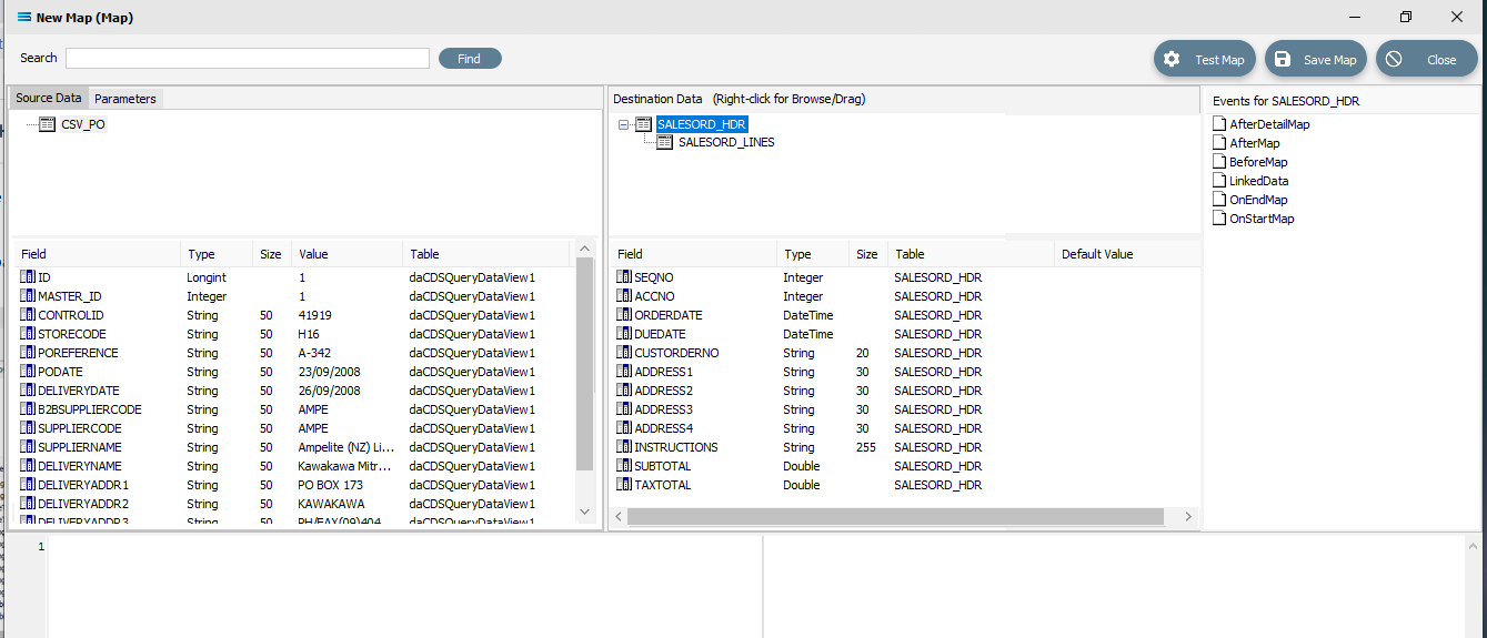
If you click on CSV_PO in the Source pane you will see the field names that are in the CSV file appear in the lower part of the pane. Expand the pane if required.
If you click on SALESORD_HDR in the Destination Data pane, the fields in this dataset will appear in the lower part of the pane.
Link The fields
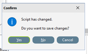
Click on SALESORD_HDR in the Destination Data pane. Then click on ACCNO in the Field list in the lower pane. Set the ACCNO field value manually to 1. Do this by clicking anywhere in the Scripting Area panel and Statelake will generate code. Append to the third line and type 1 immediately after the Value :=.

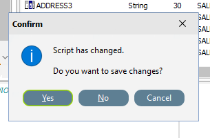
procedureOnMapEvent(varValue:variant);//ACCNObeginValue :=1end;When you click on another field name in the Destination pane, you will be prompted to save your changes. Click Yes.
ACCNO has now changed to GREEN. Now link the fields using the same drag and drop technique used previously - drag the fields from the Source Data CSV_PO and drop onto the Destination Data field belonging to SALESORD_HDR, making sure that the destination field is highlighted before dropping the source field onto it, else the link will not be successfully established. Click on CSV_PO and SALESORD_HDR to bring up the correct series of fields, then drag and drop -
CSV_PO_PODate to ORDERDATE
CSV_PO_DeliveryDate to DUEDATE
CSV_PO_POReference to CUSTORDERNO
CSV_PO_DeliveryName to ADDRESS1
CSV_PO_DeliveryAddr1 to ADDRESS2
CSV_PO_DeliveryAddr2 to ADDRESS3
CSV_PO_DeliveryAddr3 to ADDRESS4
CSV_PO_Instructions to INSTRUCTIONS
For each successful field drop, the colour of the field name in the Destination Data pane changes to GREEN, and an OnMapEvent procedure appears in the Scripting Area. In the Field Events pane, a set of events for each field has appeared, and each successful link is indicated by the OnMap event file icon being shown in GREEN.
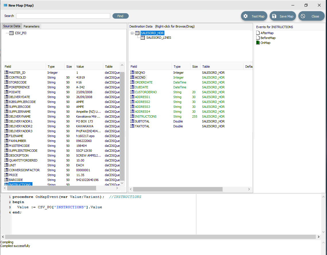
The SALESORD_HDR.SUBTOTAL and SALESORD_HDR.TAXTOTAL fields are not populated through this drag-and-drop process. They need to be manually set to 0 (zero) as these totals are not given in the source file and need to be calculated. Click on the SUBTOTAL field in the lower destination pane, then click anywhere in the Scripting Area panel to generate the code. Append to the third line and type 0 (zero) immediately after the Value :=.
procedureOnMapEvent(varValue:Variant);//SUBTOTALbeginValue :=0end;When you click out of the Scripting Area onto the SALESORD_HDR.SUBTOTAL field or another SALESORD_HDR field, you will be prompted to save your changes. Click Yes.
Now click on the TAXTOTAL field and repeat the process, appending a 0 (zero) to the Value := line.
procedureOnMapEvent(varValue:Variant);//TAXTOTALbeginValue :=0end;And again, when you click out of the Scripting Area onto the SALESORD_HDR.SUBTOTAL field or another SALESORD_HDR field, you will be prompted to save your changes. Click Yes.
Now that the mapping of SALESORD_HDR is complete, the fields in SALESORD_LINES need to be mapped as well. Click on SALESORD_LINES in the upper Destination Data pane to bring up the relevant destination fields in the lower pane.
The value for SALESORD_HDR .SEQNO will be automatically generated by the Statelake process, and SALESORD_LINES.HDR_SEQNO is set as a Foreign Key in the DB Definition, so the value will be automatically populated from the linked related field from SALESORD_HDR.
The following remaining fields will be linked by the drag-and-drop process. Each successful drop will generate some script and the Destination Data pane field names will change to GREEN.
CSV_PO_SupplierItemCode to STOCKCODE
CSV_PO_Description to DESCRIPTION
CSV_PO_QuantityOrdered to ORD_QUANT
CSV_PO_Price to UNITPRICE
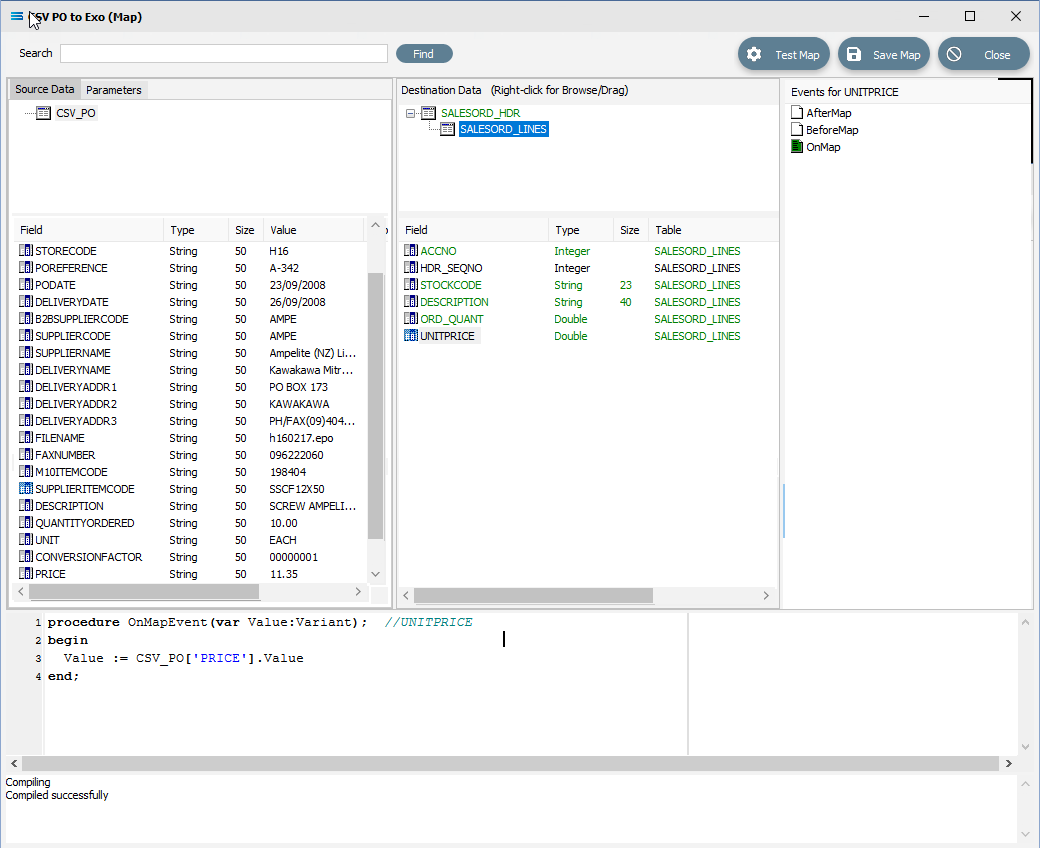
In the destination fields pane, click on ORD_QUANT, and change the end of line 3 of the script from .Value to .AsFloat to force a data type conversion.
procedureOnMapEvent(varValue:Variant);//ORD_QUANTbeginValue := CSV_PO['QUANTITYORDERED'].AsFloatend;Then click on SALESORD_LINES.UNITPRICE, and you will be prompted to save your changes. Click Yes.
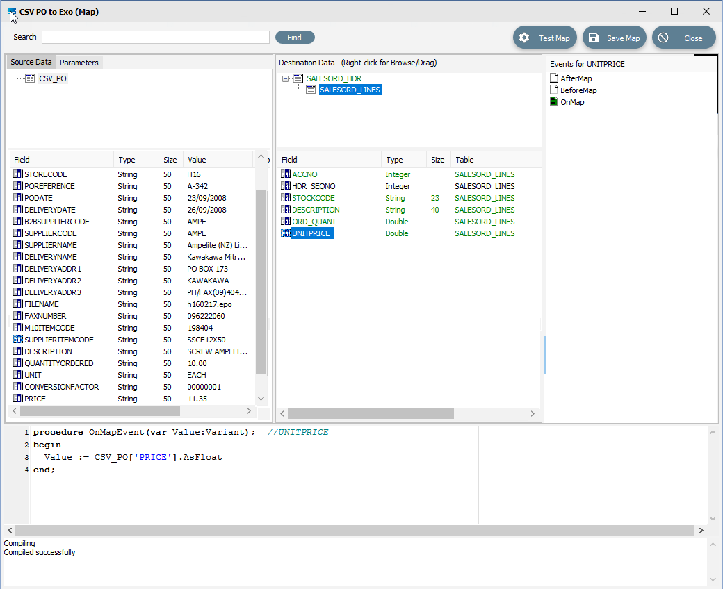
Now that UNITPRICE is selected, change the end of line 3 of the script from .Value to .AsFloat to force a data type conversion.
procedureOnMapEvent(varValue:Variant);//UNITPRICEbeginValue := CSV_PO['PRICE'].AsFloatend;Click on another field such as UNITPRICE in the upper pane, and you will be prompted to save your changes. Click Yes.
Set Up The Master Record Change
The next step is to generate script that will write the relevant records from the source CSV_PO, splitting them as appropriate between the parent dataset SALESORD_HDR and child dataset SALESORD_LINES. We do this by using a function that is particular to Statelake, called ProcessMasterRecord.
When the mapping first starts, a header record is processed in the destination (it is pull based mapping running off the destination dataset). The header has no LinkedData, therefore one record will be processed only. During processing of this record, any reference to source fields will read values from the first record in the source. The current value of the key field is stored in a global variable for later comparison.
After the header, it will start to process the child dataset. Since the LinkedData is set to the source dataset, it will continue processing the lines either until there are no more, or until the ProcessMasterRecord is called (due to change in key field value).
ProcessMasterRecord causes the script engine to start processing the header record again.
This time, any reference to source fields will be reading values from the current record in the source (The first record with the new key field). Again after the header is processed it will continue to process the lines.
ProcessMasterRecord is only available in the BeforeMapEvent of a dataset. By calling this function, the program flow loop is broken and control returned to the next level up, so processing will revert to the parent dataset.
The function is used to process the source definition CSV Purchase Order - a single dataset of lines needing to be split into a destination definition that has the header and line datasets, SALESORD_HDR and SALESORD_LINES. The source dataset has the key field POReference that holds the same data across lines in the same group e.g. the source is an order line, so every line will have this order number field. Each time the order number changes in the source dataset, you will need to create a new record in the destination header dataset SALESORD_HDR.
You will need to configure your Map in the following way. Click on SALESORD_HDR in the upper destination pane to make this the active dataset.
Click on the BeforeMap icon in the Events for SALESORD_HDR pane. Click anywhere in the Scripting Area and code will be automatically written as below.
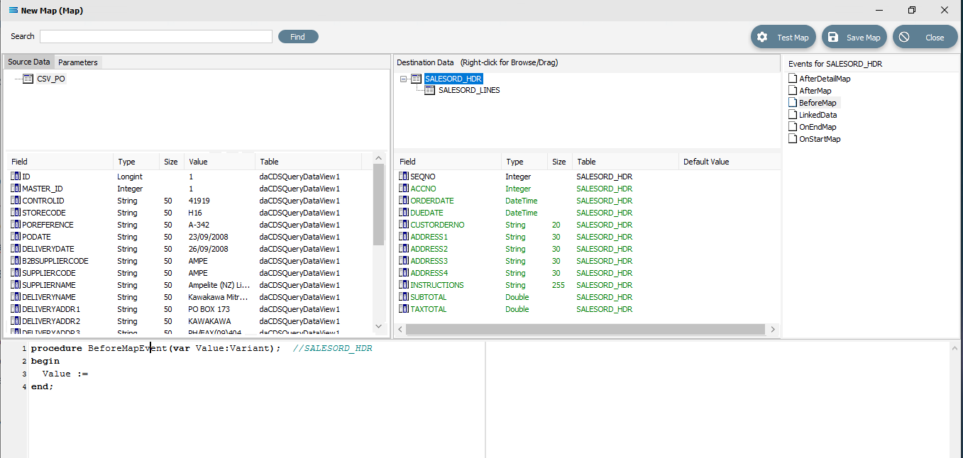
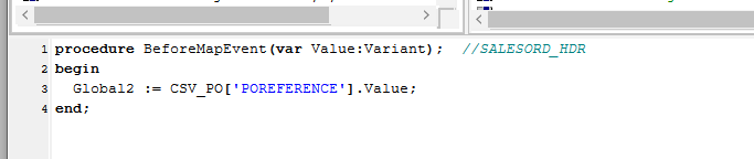
Click into the Scripting Area, and replace the auto‑generated code with the following. Replace Value := with Global2 :=. Then pick up and drag POReference from the source dataset and release at the end of the := adding a final semi-colon (;), making the line read as Global2 := CSV_PO['POREFERENCE'].Value;
procedure BeforeMapEvent(var Value:Variant); //SALESORD_HDRbegin Global2 := CSV_PO['POREFERENCE'].Value;end;Click back onto SALESORD_HDR and when prompted to save the changed script, reply Yes. This script resides on the BeforeMap event of the parent dataset. It stores the key field's value in a global variable.
The pre-defined special Statelake variables called Global1 through to Global10 (Global1, Global2, Global3, Global4, Global5, Global6, Global7, Global8, Global9, Global10), are what are known as Global Variables. Please review Global Variables for more information. And while they are available across all Maps, and are accessible in any Map, the values they hold carry across to all parts of the current Map only. For example, if you have two (2) Maps, and within one you set Global1 to have the value of 25, you will not be able to access this value through Global1 in the second Map.
We are using Global2 for the POReference because Global1 will be used for the order total.
We now to connect the source dataset CSV_PO to the child destination dataset SALESORD_LINES, creating a LinkedData event, by dragging the source dataset CSV_PO onto the destination child SALESORD_LINES. Click on CSV_PO and drag it over. The script that appears is as follows.
procedure LinkedDataEvent(var LinkedData:TdaQueryDataView); //SALESORD_LINESbegin LinkedData := CSV_PO;end;Now click on the BeforeMap icon in the Events for SALESORD_LINES pane. Click anywhere in the Scripting Area and code will be automatically written as below.
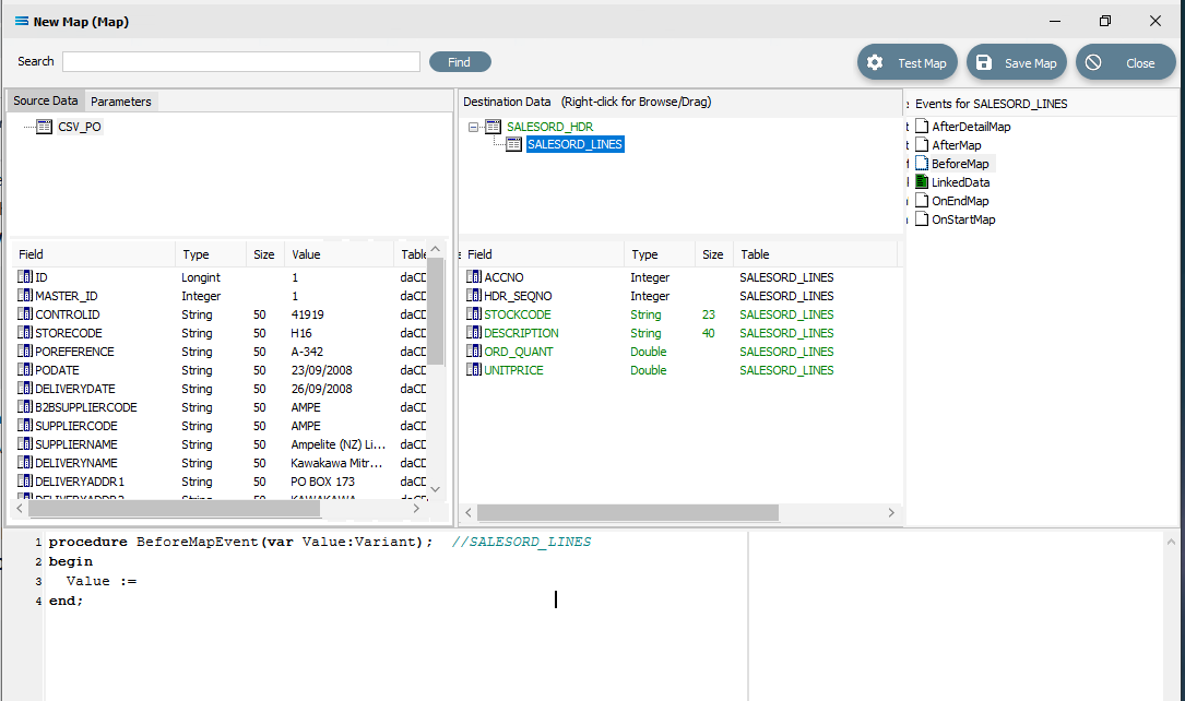
We want to change this script so that each time a line is processed, a check is performed to see if the source key field POReference holds the same value in the SALESORD_LINES dataset. If the value has changed to indicate that the current record is a line for a different order, then the function ProcessMasterRecord needs to be called to start a new header record. Replace the code in the script window with the following code.
procedure BeforeMapEvent(var Value:Variant); //SALESORD_LINESbegin If Global2 <> CSV_PO['POREFERENCE'].Value then begin ProcessMasterRecord; Exit; //call Exit to stop this script now and start on the header immediately end;end;Right-click anywhere in the script window and select Test Compile to check the syntax. Make any changes as required.
When the script compiles without error, click back on the SALESORD_LINES dataset and reply Yes when prompted to save.
Create Detailed Scripts
Although the value for SALESORD_LINES.ACCNO is already specified on SALESORD_HDR, the mapping script for this field needs to be manually set. With the SALESORD_LINES dataset selected and its fields displayed, click on ACCNO. The digit 1 will appear in the margin of the Scripting Area.
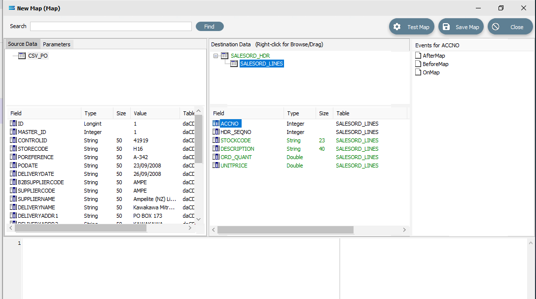
Click anywhere in the Scripting Area to generate the base code.
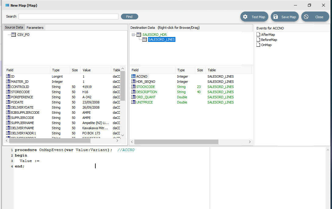
If this “empty” base code fails to generate and just the number 1 continues to be displayed in the scripting window, go to the Events for ACCNO pane in the top right of the window, and right-click on the GREEN OnMap icon - the icon itself, rather than the words OnMap. Select Clear from the pop-up. This will reset the script window so that you can try loading the base script again by clicking anywhere within the scripting window while SALESORD_LINES.ACCNO is selected in the destination pane.
With this code still active, we need to swap over control to access the field name in SALESORD_HDR. To achieve this, follow these steps – be aware, it is easy to lose track of where you are! The dataset SALESORD_LINES in the Destination Data pane should still be highlighted. Right-click on SALESORD_HDR in the Destination Data pane to give control over to this dataset. You should get the cursor to change to a diagonally-barred circle. The relevant fields belong to this dataset will appear in the lower pane.
Now left-click with your cursor in the blank space in the top right hand side of the top Destination Data pane. A right-click would usually copy and a left-click will normally paste. But as we are using this right‑click to simply swap datasets, the copy/paste is not required. You will see that the Scripting Area still displays the code that we generated for the ACCNO field in SALESORD_LINES - the code does not change.
But now we do want to copy/paste, so right-click on SALESORD_HDR.ACCNO as is displayed in the lower portion of the Destination Data pane to copy the field name. You should get the cursor to change to a diagonally-barred circle beside ACCNO. The field is picked up. Then left-click with your cursor in the Scripting Area at the end of the 3rd line to append the field name to the Value := to post/append this code to the end of the line.
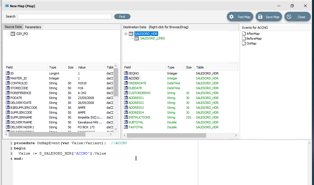
The code should now be as below. The D_ denotes that the field is from a destination dataset. A close up of the code follows.
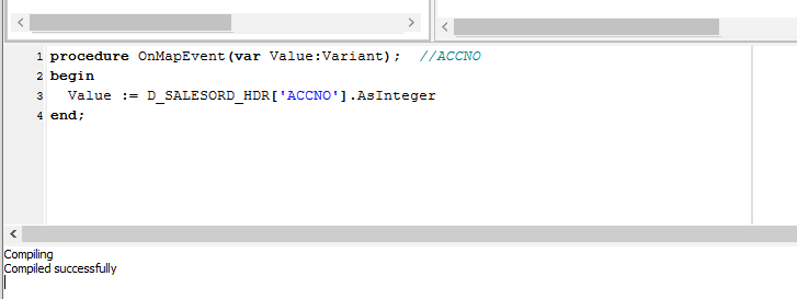
procedureOnMapEvent(varValue:Variant);//ACCNObeginValue := D_SALESORD_HDR['ACCNO'].Valueend;The line needs one further amendment. The .Value at the end of the line that you have just pasted, needs to be replaced by .AsInteger, so the code matches the example below.
procedureOnMapEvent(varValue:Variant);//ACCNObeginValue := D_SALESORD_HDR['ACCNO'].AsIntegerend;Right-click anywhere in the Scripting Area pane to select Test Compile and check that the code is correct.
To verify that this code applies to ACCNO in SALESORD_LINES, click on the SALESORD_LINES dataset. You will be prompted to save your script changes – click Yes. Then click on the field ACCNO. This field should now display in GREEN and the compiler area should show that the code has been successfully compiled. If the compile fails, check your spelling and try again.
There are two fields in SALESORD_HDR that need further modifications to their script code. ORDERDATE and DUEDATE are presented as strings in the input/source dataset, but as the destination/output stores these values need to be proper dates, so these strings need to be converted into the DateTime data type using the StringToDateTime function. Click on SALESORD_HDR to load the fields into the lower pane.
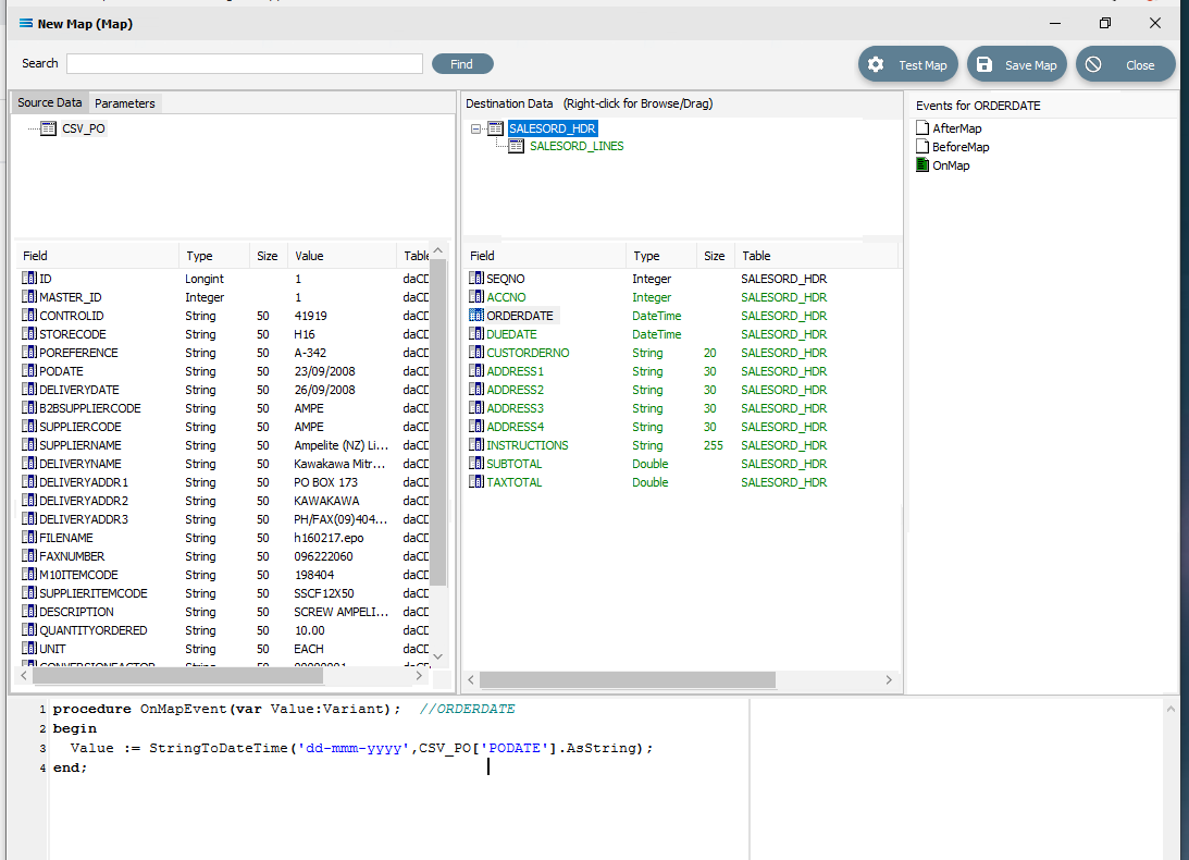
Click on ORDERDATE to display the OnMapEvent code in the Scripting Area. We want to change line 3 of the code from Value := CSV_PO['PODATE'].Value to the following code.
 Close up of the replacement script.
procedureOnMapEvent(varValue:Variant);//ORDERDATEbeginValue := StringToDateTime('dd-mmm-yyyy', CSV_PO['PODATE'].AsString);end;When you click out of the Scripting Area, if you are prompted to save your changes, click Yes. This field should still display in GREEN.
To test your scripting so that you know it holds no errors and will compile successfully, you can right-click in the blank space of the scripting area, and select Test Compile from the list at any time.
Click on DUEDATE to display the code in the Scripting Area. Change line 3 in the script in the same manner, so as it reads as below.
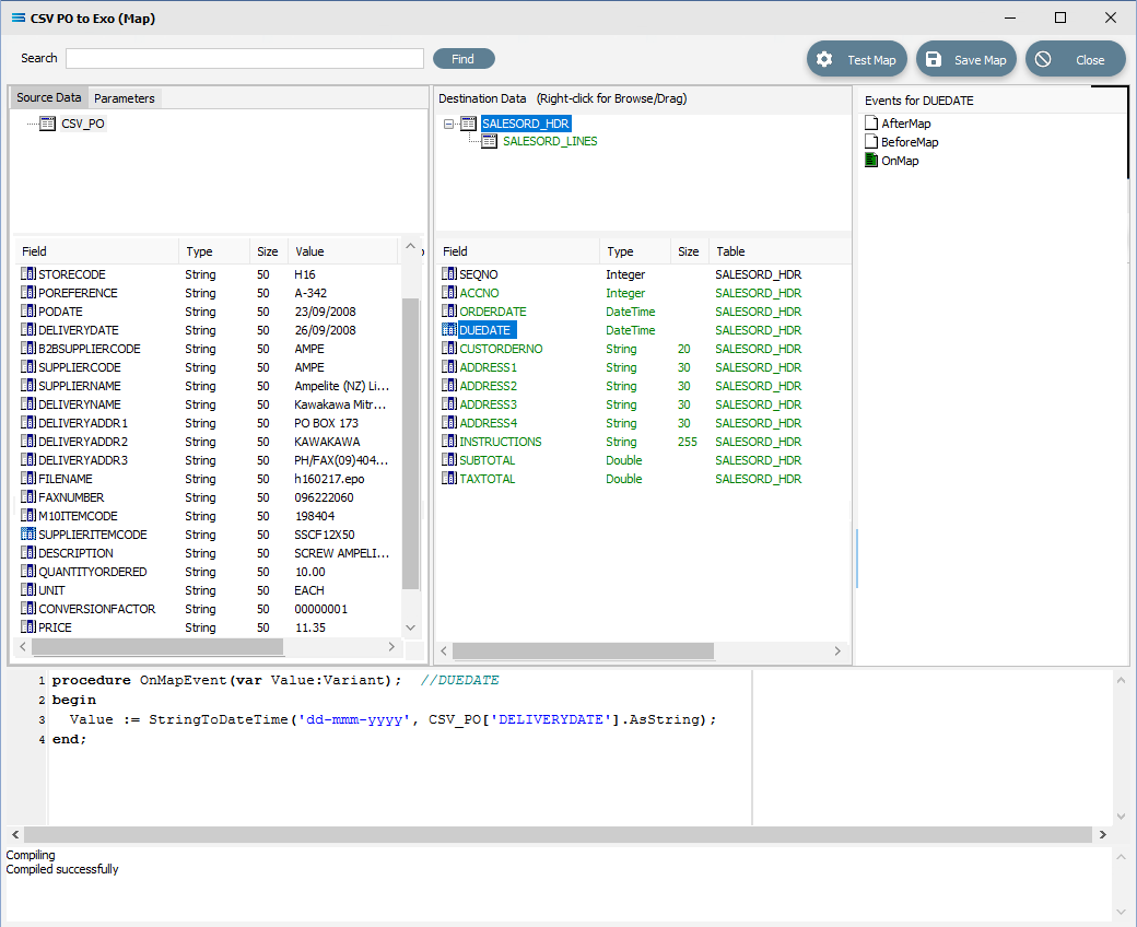
procedure OnMapEvent(var Value:Variant); //DUEDATEbegin Value := StringToDateTime('dd-mmm-yyyy', CSV_PO['DELIVERYDATE'].AsString);end;When you click out of the Scripting Area, if you are prompted to save your changes, click Yes. This field should be displayed in GREEN.
Make sure that when you amend this code that you use the correct type of quote marks, else the script will not compile. Beware of copy and paste from a text editor. The correct quote marks should be single quotes and be strictly vertical such as '.
To facilitate the orders totals mapping, a running order total calculation needs to be added as an AfterMap event on the SALESORD_LINES dataset. This introduces two new concepts: variables and logging. Firstly, the total for the current line is calculated and stored in the local variable vLineValue, which exists only within the event script. It is then added to the running total stored in the variable Global1, which is accessible in all event scripts in the Map. The results of the calculations from these two variables are output to the log.
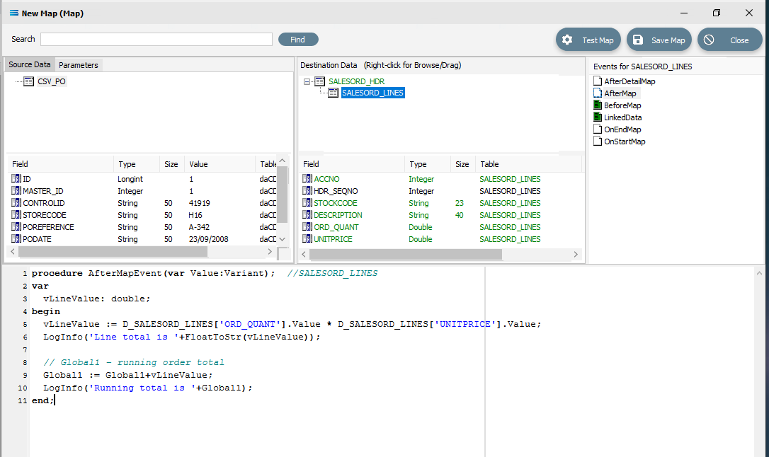
Click on SALESORD_LINES to make that dataset the current active dataset. Click on the AfterMap icon in the Events for SALESORD_LINES pane. Click your cursor anywhere within the Scripting Area, and the following code should appear.
procedureAfterMapEvent(varValue:Variant);//SALESORD_LINESbegin// The AfterMap event will fire even for records that are skipped by setting Value:=False// in the BeforeMap. To run AfterMap code only for records that were not skipped wrap your// code with the following commented check// if Value then// Begin//End;Value :=end;Change the code to the following. If you prefer, you can leave the lines that are pre-fixed by two diagonal lines // because they are just comments. But for tidiness in this tutorial, they are removed or replaced.
 Close up of the code as below.
procedureAfterMapEvent(varValue:Variant);//SALESORD_LINESvarvLineValue:double;beginvLineValue := D_SALESORD_LINES['ORD_QUANT'].Value * D_SALESORD_LINES['UNITPRICE'].Value;LogInfo('Line total is '+FloatToStr(vLineValue));// Global1 – running order totalGlobal1 := Global1+vLineValue;LogInfo('Running total is '+Global1);end;Make sure that your lines of code do not wrap onto a second line because this will affect the way that the script is read and processed. After entering the code as above, right-click in the Scripting Area and select Test Compile to verify that there are no errors and that the code has compiled successfully. Then click on another field name in the Destination Data pane, and if you are prompted to save your changes, click Yes. To see this code, click on the AfterMap icon in the Events for SALESORD_LINES pane.
However, just having a total in the variable is not enough. It has to be assigned to a destination field. This is done in the AfterDetailMap event for the SALESORD_HDR dataset. Click on SALESORD_HDR to make that dataset the current active dataset. Click on the AfterDetailMap icon in the Events for SALESORD_HDR pane. Position your cursor in the Scripting Area, and the following code should appear.
procedureAfterDetailMapEvent(varValue:Variant);//SALESORD_HDRbeginValue :=end;Replace this code with the following to assign the values of the variables to the fields in the destination.
procedureAfterDetailMapEvent(varValue:Variant);//SALESORD_HDRbeginD_SALESORD_HDR['SUBTOTAL'].Value := Global1;D_SALESORD_HDR['TAXTOTAL'].Value := Round2Up(TaxAmount(Global1,15),2);end;Again, you can Test Compile to error check your code. A successful compile will change the event icon to GREEN. Click on any field or node name in the Destination Data pane to save your script. Again, when prompted to save the script, reply Yes.

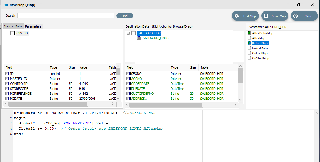
Finally, the running total variable Global1 must be reset to zero for every order that is processed. To do this, code must be entered for a BeforeMap event in the SALESORD_HDR dataset. If not still selected, click on SALESORD_HDR to make the dataset the current active dataset. Click on the BeforeMap icon in the Events for SALESORD_HDR pane. The script will currently read as follows.
Click into the Scripting Area, and add this additional line as below to change the current script.
procedure BeforeMapEvent(var Value:Variant); //SALESORD_HDRbegin Global2 := CSV_PO['POREFERENCE'].Value; Global1 := 0.00; // Order total; see SALESORD_LINES AfterMapend;The comment after the 2 diagonal slashes on the 3rd line will be read only, and will not be processed. Right-click while still in the Scripting Area to Test Compile to error check your code. Click on any field name in the Destination Data pane to save your script. To check the code, you can click on the BeforeMap event icon for the SALESORD_HDR dataset.
The last field to be still lacking proper mapping is ACCNO in the order header table SALESORD_HDR. The order file does not include the account number from the system that we are importing into, so we need to determine what this number is, based on another key field. In this tutorial, this key field is called STORECODE. The EXO system into which the data is being imported, stores these codes against the debtor accounts in the BRANCH field. This next step will add the appropriate mapping to determine the value in SALESORD_HDR.ACCNO, and reject the order if the account cannot be found or identified. To make this action possible, additional code needs to be added to the BeforeMap event on SALESORD_HDR – including introduction of another global variable. Click on SALESORD_HDR to make the dataset the current active dataset.
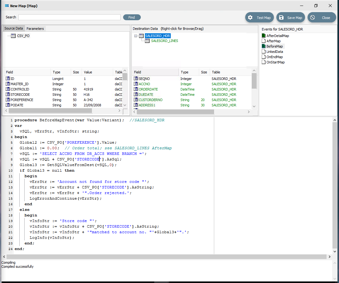
Click on the BeforeMap icon in the Events for SALESORD_HDR pane. The code that you have just edited will display in the Scripting Area. Replace the code with the following code to make a query on the destination database, and then store the returned value in the variable Global3. Then the value of the variable is checked to determine whether to proceed with the order or reject it.
procedureBeforeMapEvent(varValue:Variant);//SALESORD_HDRvarvSQL, vErrStr, vInfoStr:string;beginGlobal2 := CSV_PO['POREFERENCE'].Value;Global1 :=0.00;// Order total; see SALESORD_LINES AfterMapvSQL :='SELECT ACCNO FROM DR_ACCS WHERE BRANCH =';vSQL := vSQL + CSV_PO['STORECODE'].AsSql;Global3 := GetSQLValueFromDest(vSQL,0);ifGlobal3 = nullthenbeginvErrStr :='Account not found for store code "';vErrStr := vErrStr + CSV_PO['STORECODE'].AsString;vErrStr := vErrStr +'".Order rejected.';LogErrorAndContinue(vErrStr);endelsebeginvInfoStr :='Store code "';vInfoStr := vInfoStr + CSV_PO['STORECODE'].AsString;vInfoStr := vInfoStr +'"matched to account no. "'+Global3+'".';LogInfo(vInfoStr);end;end;After entering the code as above, right-click and Test Compile. The message “Compiling” and “Compiled successfully” should appear on separate lines in the messages pane. Correct any error and re-test until the code is accepted.
Then click on any field or table name in the Destination Data pane to save your script. Reply Yes to the prompt to save the script.
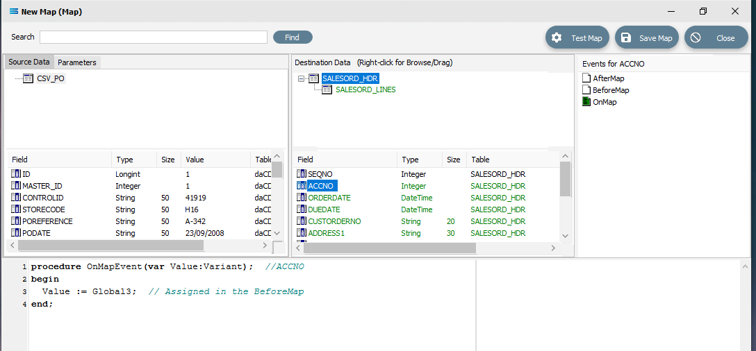
You are on the home straight. To complete the mapping, the value of the variable Global3 needs to be assigned to SALESORD_HDR.ACCNO. Ensure that SALESORD_HDR is the current active table. Click on the field ACCNO from the lower Destination Data pane. Replace the code in the Scripting Area with the following:
procedureOnMapEvent(varValue:Variant);//ACCNObeginValue := Global3;// Assigned in the BeforeMapend;The comment on the line will be ignored and not processed. Click on SALESORD_HDR.ACCNO in the Destination Data pane to save the script. Reply Yes when prompted to save the script.
Now save the Map and commit all of the mapping and scripting by clicking Save Map in the top right corner. Select OK to close the successful save message, then click on the Close button to close the map designer window.
Make sure that the Map has a name - CSV PO to EXO.
To commit all the mapping and scripting, click Save to save and close the mapping module.
The Map named CSV PO to EXO will now appear in the structure tree under Configuration > Components > Maps.
Test The Map
Now test the Map to ensure it is working:
Open the Maps module again by clicking on CSV PO to EXO, and click on the Design button.
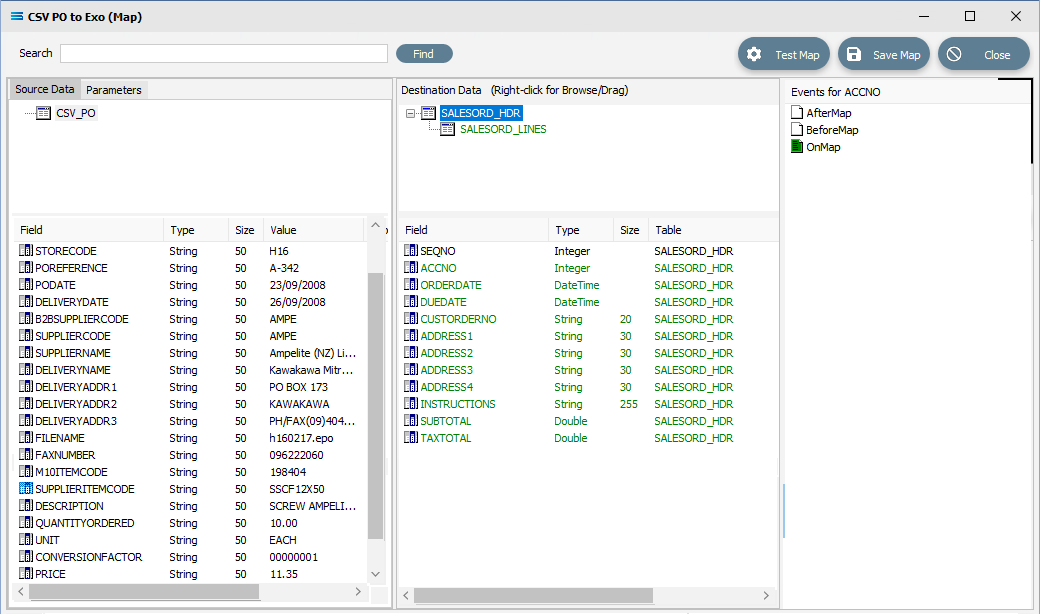
The Map Designer screen called CSV PO to EXO (Map) will display, with only the Source data CSV_PO showing, and SALESORD_HDR showing under Destination Data. SALESORD_HDR will be displayed in GREEN.
As a quick check, if the required file is not present in the selected directory, then there will be no entries in the Value column of the POdetail table in the Source pane.
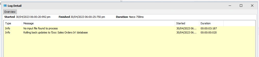
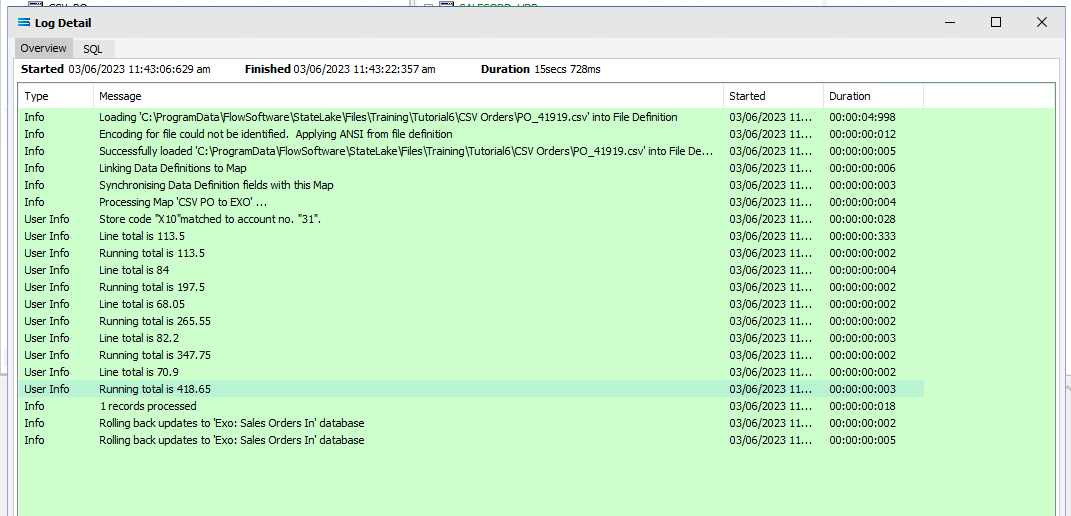
Click Test Map in the top right corner of the screen, to execute the Map in memory and generate a processing log which is then presented in a preview pane. If there is no data selected, then the Log will have a pale YELLOW background. If this occurs check your definitions, change whatever is incorrect, and try the test again. Outright errors will have a dark PINK background, but with a successful test, the background will be pale GREEN. Examples of these log file colours are below.
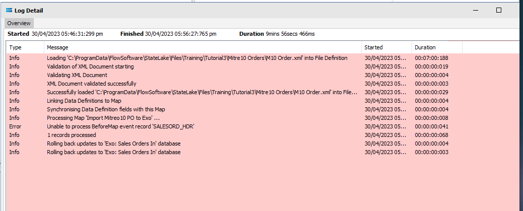
When you are testing the Map (or in due course running the associated Action), and encounter an error that produces a PINK Log file, make sure to carefully read the details that are provided around the error. This tutorial has one file that has been set up to fail intentionally, so depending on which file you are processing, this may be the cause of the error. The error message that is generated in this case, was entered as part of a BeforeMap event on SALESORD_HDR in item #21 in the previous section.
Close the pop-up preview of the log and the definition Exo: Sales Orders In window will be open.
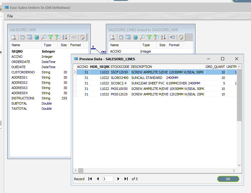
The query SALESORD_HDR and SALESORD_LINES linked to SALESORD_HDR will be displayed on the canvas. Click on the Preview button on SALESORD_HDR to view the processed records.
Using the X in the upper right corner, close the Preview Data pane, or click OK.
Click on the Preview button on SALESORD_LINES linked to SALESORD_HDR to view the processed records.
Using the X in the upper right corner, close the Preview Data pane, or click OK.
Select File Close on the canvas, then the Close button on the Map Designer screen for CSV PO to EXO (Map), and the Cancel button on the CSV PO to EXO (Map) data entry window.
The Map has now been configured to insert two-level records into EXO from a single-level CSV source file. The links have been tested in memory to ensure that the Map has all the information required for a successful extraction.
However, no actual file to database updates have occurred.
The next step pulls all the configured components together to produce the destination tables.
What Action To Take - Creating An Action
The final step is to pull all the definitions and configured components together to form an executable process to produce the destination database. This process is called an Action. While the details for an Action can be created manually, Statelake can also generate the Action quickly and easily for you.
Designer will already be open. If not, open the Statelake module Designer for the selected configuration called Statelake_Training. An expanded structure tree is displayed on the left side of the screen.
Create The Action Automatically
Follow the path Configuration > Components > Maps. Right‑click on the Map you have just created CSV PO to EXO (Map), and choose Create Action from the drop‑down list. All the relevant components will be automatically added to this Action.
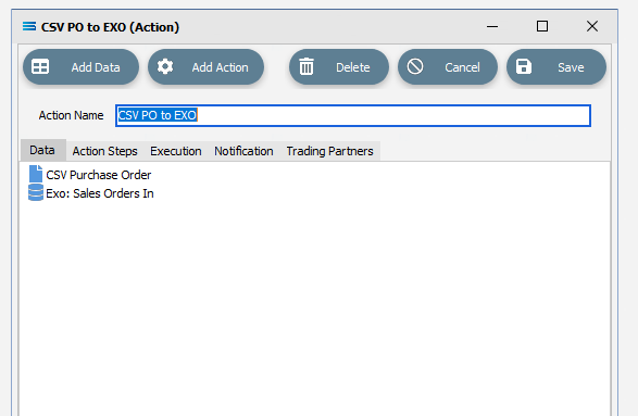
There is no need to do anything with this window, except select Save on the top right corner to close the module.
The Action named CSV PO to EXO will now appear in the structure tree under Configuration > Actions.
Run The Action
To run this Action, under the Actions directory, right-click on CSV PO to EXO, then select Run Action from the available options.
A window will pop-up showing the processing steps in a preview log, that will show the steps that were completed, how many records were extracted and processed, and where the destination file was saved. When the Action has been completed a status message will pop-up on screen indicating that processing is complete, and advising whether the process was successful or an error was encountered. You will see that this log references the first file PO_41919.csv.
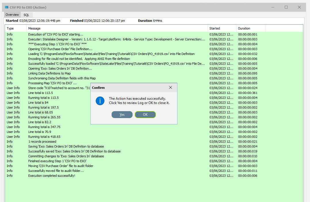
A successful Action will offer two choices – click Yes to review the log, or click OK to close the log without review. To close the Log after review, click the X in the upper right corner.
Logs can be opened at any stage as many times as required. To review a Log from the Manage Logs window, double-click on the Log required. To drill into any line of the selected Log, double-click on the line to see more detail.
Once the file has been successfully processed, it is automatically moved into the AUDIT sub-directory as specified on the File Connection. If the processing found an error, then the file is automatically removed into the ERROR sub-directory.
We know that there are 2 files - PO_41919.csv and PO_41920.csv. The Action will only run on one file at a time. There is a setting that allows the automatic processing of multiple files allowing Statelake to continue processing multiple files, but we are not using this in this tutorial.
So this first Run Action has only processed PO_41919.csv, and will need to be run again to process the only remaining file PO_41920.csv. PO_41919.csv is .set up to cause an error and the Log file will be PINK.
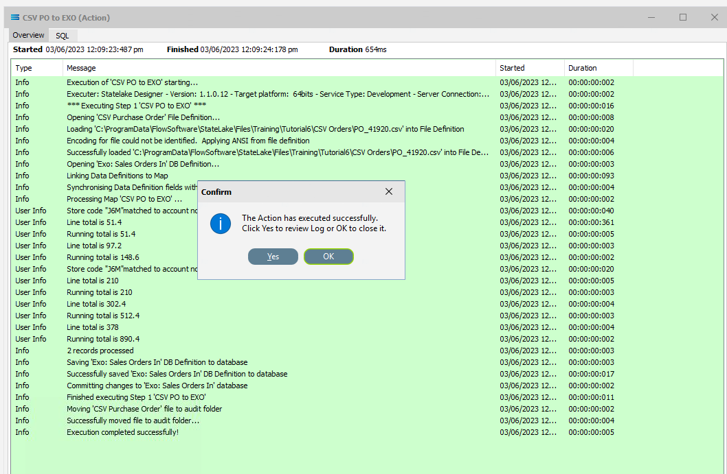
To run the Action for the 2nd file, PO_41920.csv, right-click on CSV PO to EXO and select Run Action. When you run the Action once more, the file PO_41920.csv will be processed and it will be successful, generating a GREEN Log file.
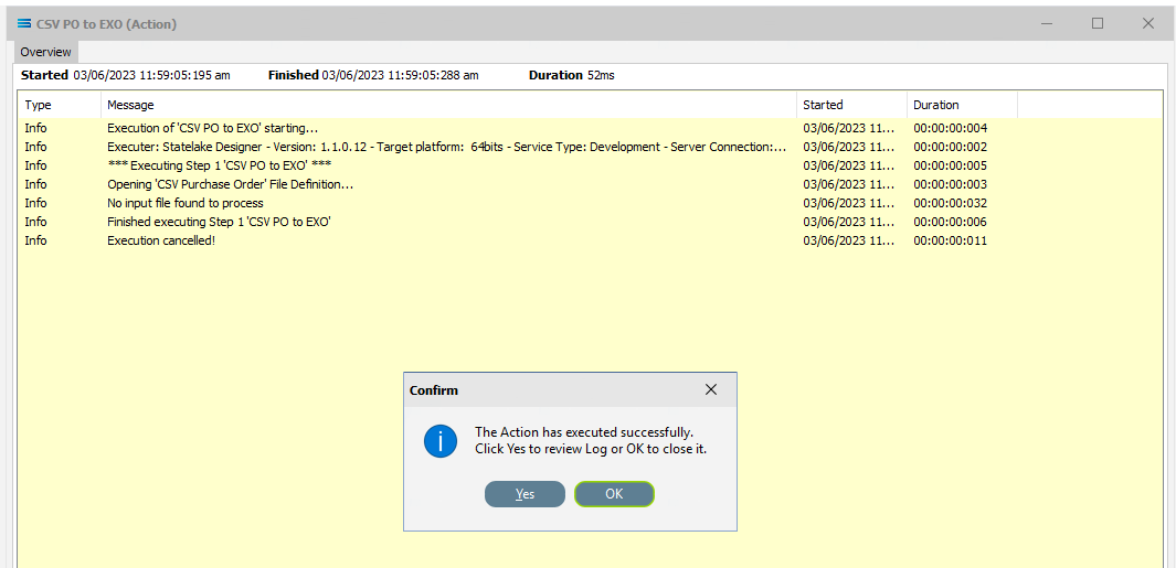
There are now no more CSV files to process as both have now been moved to the AUDIT sub-directory. So on a third processing of Run Action when there are no longer any files remaining in the directory, the Log will show YELLOW, indicating there were no records found to process.
The process is now complete, all modules have been closed, and the structure tree will be the only item on the Designer screen.
Summary
Congratulations! You have successfully generated a two-level database table from a single-tier CSV source file. Well done.
In summary these are things that have been achieved for this configuration in this tutorial:
A flat CSV file definition has been configured to enable reading of the multiple CSV files.
A database definition has been configured to enable writing into related database tables.
Various events have been introduced during mapping.
The use of variables in the mapping script.
Data conversion during scripting.
Querying databases from the map during processing.
Quick Recap Quiz
This was a complicated multi-faceted tutorial, which called for focus and concentration to perform all the various steps successfully. See if you can answer these quiz questions!
Source and destination data structures are linked by drag-and-drop to create what relationship?
a. LoadFile b. LinkedData c. DataDrop
2. In a File Connection, how many different directories are required to be created?
a. 3 b. 2 c. 1
3. A flat file has how many tiers (or layers)?
a. 1 b. 2 c. 3
4. Which Statelake module details how the output is to be created?
a. Action b. Definition c. Map
5. How do you de-select a field in a dataview query?
a. Delete it b. Double-click it c. Re-name it
6. Field names in the Query Designer are forced to what case?
a. Upper case b. Lower case c Sentence case
7. This tutorial demonstrates the process importing from a CSV single-tier file, into what type of destination?
a. EXO database b. XML file c. Flat file
8. In the Query Designer, what colour denotes a calculated or automatically generated field?
a. Green b. Blue c. Red
9. What colour is the log background when no records have been identified
a. Pink b. Yellow c. Green
10. The variables Global1, Global2, and Global3 are known as what type of variable?
a. Global b. Local Global c. Local
Next Steps
Congratulations on your progress to date.
The Statelake tutorial series continues with other exciting stand-alone tutorials.
To keep the knowledge you have so far gained fresh in your mind, we recommend that you continue to practice or refresh with these tutorials whenever possible.
Quick recap quiz answers
b 2. a 3. a 4. c 5. b 6. a 7. a 8. c 9. b 10. a